MDS 05-3316A01, Rev. E MDS 4710B/9710B I/O Guide 13
3. If not done earlier, refine the antenna heading of the station to maxi-
mize the received signal strength (RSSI) from the master station.
Use the RSSI command from an HHT connected to the radio’s DIAG-
NOSTICS connector.—See TRANSCEIVER PROGRAMMING on
page 15. This can also be done with a DC voltmeter as described in
3.3 RSSI Chart
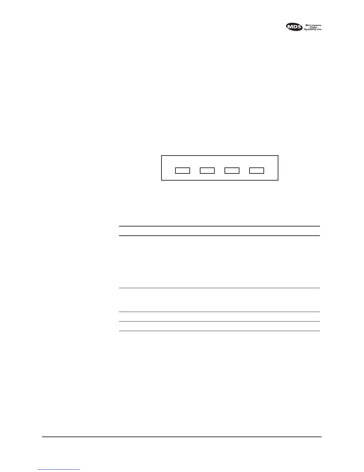
3.2 Reading LED Status Indicators
Table 6 describes the function of each status LED.
Invisible place holder
Figure 8. LED Status Indicators
Invisible place holder
PWR DCD TXD RXD
Table 6. LED status indicators
LED Name Description
PWR • Continuous—Power is applied to the radio, no faults detected.
• Rapid flash (five times-per-second)—Fault indication. Refer to
Checking for Alarms—STAT command on page 32
• Moderate flash (one time-per-second)—Internal firmware error.
Refer to Upgrading the Radio’s Software on page 37
• Off—No power is applied to the radio or the radio is in Sleep mode.
Refer to Using the Radio’s Sleep Mode on page 7
DCD • Flashing—Indicates the radio is receiving valid data frames.
• Continuous—Radio is receiving a data signal from a continuously
keyed radio.
TXD An RS-232 mark signal is being received at the DATA INTERFACE.
RXD An RS-232 mark signal is being sent out from the DATA INTERFACE.