14 MDS 4710B/9710B I/O Guide MDS 05-3316A01, Rev. E
3.3 RSSI Chart
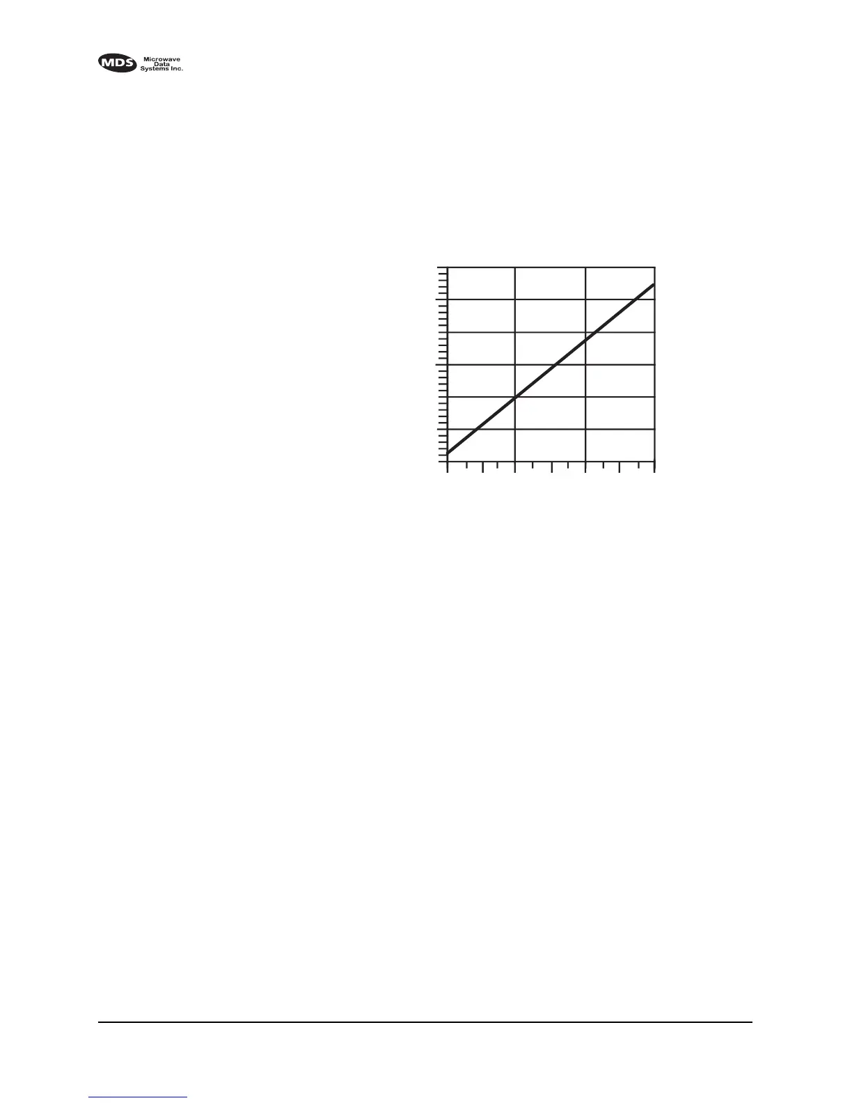
As an alternative to using an HHT, the radio’s RSSI may be read with a
DC voltmeter connected to Pin 21 of the
DATA INTERFACE connector.
Figure 9 shows the relationship between received signal level and the
DC voltage on Pin 21 of the
DATA INTERFACE connector. (Note: Read-
ings are not accurate for incoming signal strengths above –50 dBm.)
Invisible place holder
Figure 9. RSSI versus DC voltage (typical)
3.4 Remote RTU Reset
Using MDS InSite software (version 4.1 or later), a command can be
issued remotely to toggle Pin 15 of the
DATA INTERFACE connector.
From InSite:
1. Select the
SYSTEM (Network) DIAGNOSTICS POLLING from the main
menu.
2. Open the pull down menu
DIAGNOSTICS POLLING MODE and select
REMOTE MAINTENANCE.
3. Click on the particular remote radio that needs the RTU reset. The
REMOTE MAINTENANCE screen appears.
4. Click on RTU RESET LINE to set pin 15 to High or Low.
2
2.5
3
3.5
4
–110
–90
–70
–50
+ DC VOLTS (PIN 21)
SIGNAL LEVEL (dBm)
4.5
5.0