8 MDS 4710B/9710B I/O Guide MDS 05-3316A01, Rev. E
2.3 Transceiver Mounting
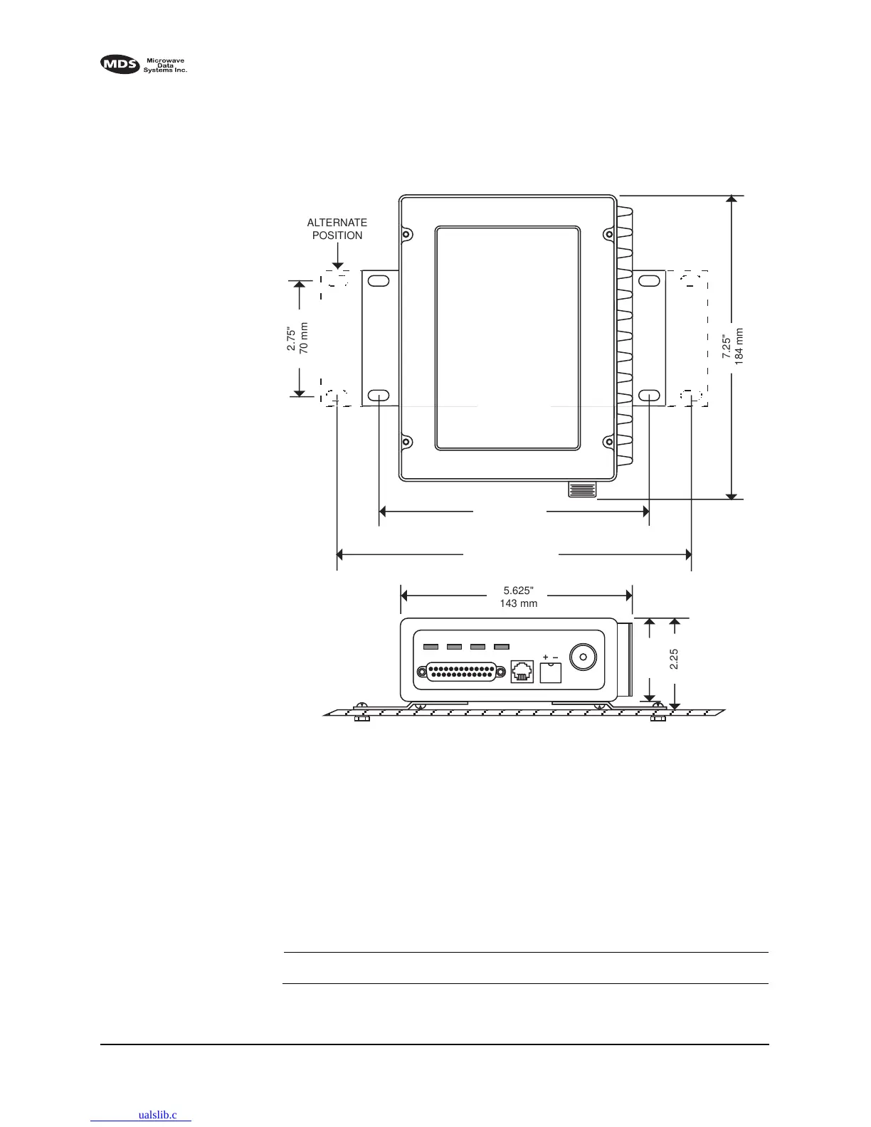
Figure 6 shows the mounting dimensions of the transceiver.
Invisible place holder
Figure 6. Transceiver mounting dimensions
2.4 Power Connection
The transceiver can be operated from any well-filtered 10.5 to 16 Vdc
power source. The power supply should be capable of providing at least
2.5 amperes of continuous current.
The red wire on the power cable is the positive lead; the black is nega-
tive.
NOTE: The radio is designed for use only in negative ground systems.
8.5"
216 mm
1.75"
4.44 CM
6.63"
168 mm
2.75"
70 mm
7.25"
184 mm
ALTERNATE
POSITION
5.625"
143 mm
2.25"
57 mm
2.0"
50 mm