36 MDS 4710B/9710B I/O Guide MDS 05-3316A01, Rev. E
1. Remove the top cover from the transceiver by loosening the four
screws and lifting straight up.
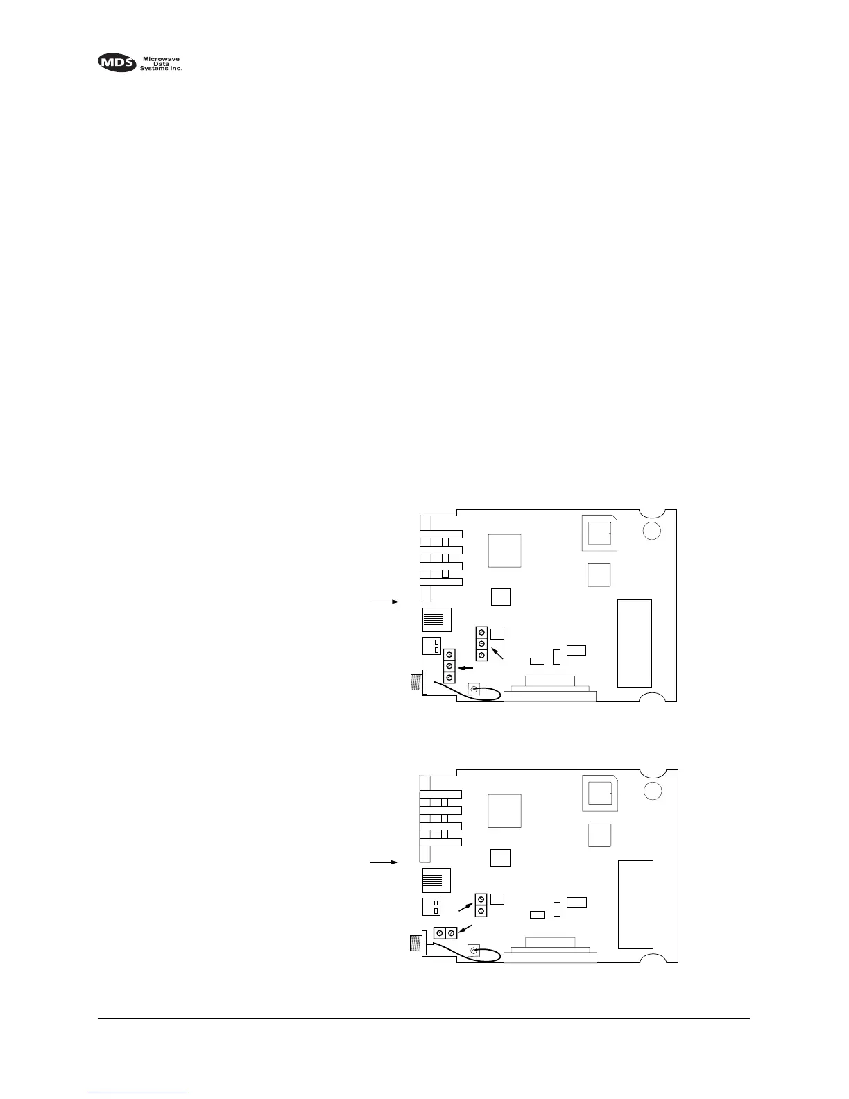
2. Locate the helical filters on the PC board. See Figure 14 (MDS
4710B) or Figure 14 (MDS 9710B) as appropriate.
3. Apply a steady signal to the radio at the programmed receive fre-
quency (–80 dBm level recommended; no stronger than –60 dBm).
This should be done with a signal generator.
4. Measure the radio’s RSSI using one of the following methods:
• With an HHT (See 4.0 TRANSCEIVER PROGRAMMING).
• With MDS Radio Configuration Software (See 7.3 Using PC
Software with the Radio).
• With a voltmeter connected to Pin 21 of the
INTERFACE connec-
tor (See 3.3 RSSI Chart).
5. With a non-metallic adjustment tool, adjust each section of the heli-
cal filters for maximum RSSI. Re-install the cover to the transceiver.
Invisible place holder
Figure 14. MDS 4710B helical filter locations
Invisible place holder
Figure 15. MDS 9710B helical filter locations
FRONT PANEL
OF RADIO
J301
U104
U101
U202
HELICAL
ADJUSTMENTS
U203
SHIELD
COVER
FRONT PANEL
OF RADIO
J301
U104
U101
U202
HELICAL
ADJUSTMENTS
U203
SHIELD
COVER