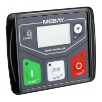
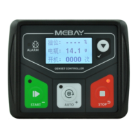
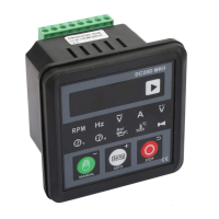
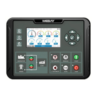
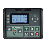
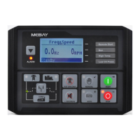
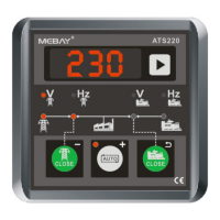
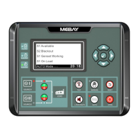
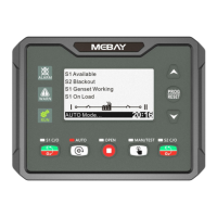
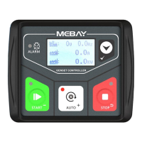
DC32D GENSET CONTROLLER USER MANUAL
9
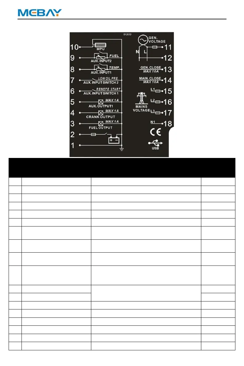
Descriptions of terminal connection
Cable cross
sectional area
Battery Negative Input B-
Controller power supply input B-.
Battery Negative Input B+
Controller power supply input B+.
Rated current 1A; power supplied by PIN 2.
Rated current 1A; power supplied by PIN 2.
Rated current 1A; power supplied by PIN 2.
Ground connected is active (B-)
Connect to low oil pressure switch input
according to function selection
Connect temperature sensor or switch
input according to function selection
Connect fuel level sensor or switch input
according to function selection
Connect to speed sensor, and shielded
wire is recommended. The other end of
speed sensor is connected to B-.
Gens voltage Input,AC30-360V.
Generator L1 active output, 10Amp max.
Mains L1 active output, 10Amp max.
Connected to the mains L1 phase.
Connected to the mains L2 phase.
Connected to the mains L3 phase.
Connected to the mains N phase.


 To Next Page