M
AVTMBITE 3 Rev 8 April 2014
8
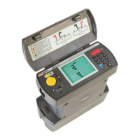
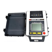
Figure-1: BITE 3 Transceiver
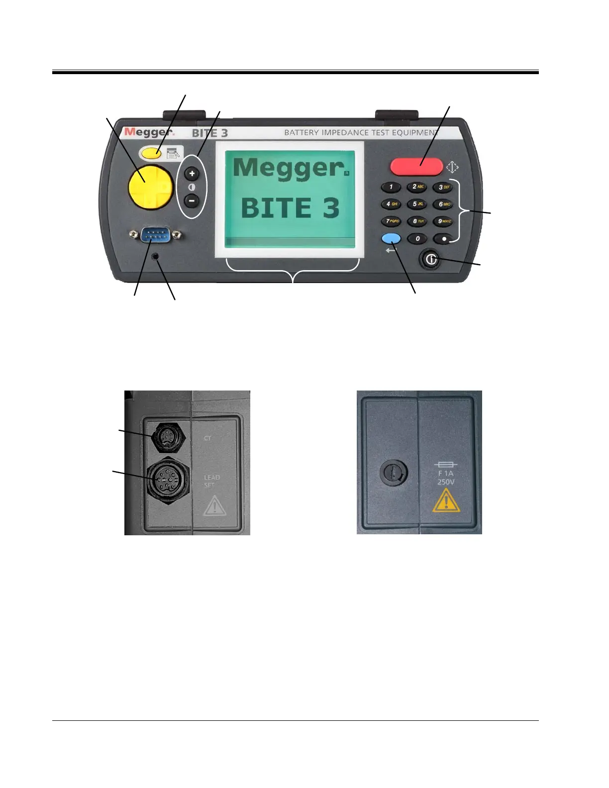
The side panels comprise the lead set connection, J1 and the CT connection, J2.
(again, the ports are not labeled Jx)
Figure-2: BITE 3 Lead Connections
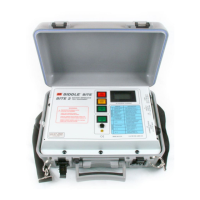
Figure 2A: BITE 3 Fuse
The battery charger connection, battery state indicator and slow charge control
are here:
1
3
4
6
7
8
9
2
10
5
J2
J1