AVTM24-1J REV A April 2006
19
Section F
CONTROLS AND CONNECTIONS
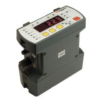
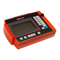
Fig. 3 shows a front panel view of Catalog No. 247000
with functional parts and operating controls labeled.
S4, M1 Battery test meter M1 shows the relative state of
charge of the internal rechargeable batteries. With
S4 in the “Display” position Ml is connected to
the battery that powers the digital meter. With S4
in the “measure’ position, M1 is connected to the
measuring circuit battery. This test is valid only
when the instrument is operating and connected
to a test specimen or with the C1and C2 leads
shorted. When the pointer indicates in the red
zone the batteries should be recharged.
S3 - The ON/OFF switch has two “ON” positions: a
“lock” position for continuous operation, and a
“momentary” spring-held position that helps
conserve battery power when taking a series of
readings on the high-current ranges.
S1 - The range switch selects one of five resistance
ranges. Panel markings are full—scale values;
nominal test currents are shown in parentheses.
M2 A 3½ digit red LED display shows the resistance
of the specimen under test. It is direct reading
with decimal points selected by a deck on the
range switch.