19
9. Insulation resistance testing
Safety notes:
Danger of electric shock: Insulation resistance testing is performed at high DC voltages and is hazardous if touched. Always observe
the safety precautions when performing an insulation resistance test, and ensure all necessary health and safety precautions are
observed.
On the MIT2500 only use the 2.5 kV test lead set on test ranges above 1 kV.
Never hold test leads when using test ranges above 1 kV.
Circuit Isolation: The circuit under test must be completely de-energized and securely isolated before test connections are
made.
Automatic Discharge: Capacitive circuits are automatically discharged when the test button is released following an insulation test.
This is a safety feature to prevent hazardous voltages remaining on test circuits after testing is completed.
Live circuit detection:
Insulation tests must only be conducted on dead, isolated circuits. However, occasionally a live circuit may be connected by accident or
isolated circuits have a voltage present through coupling to an adjacent circuit.
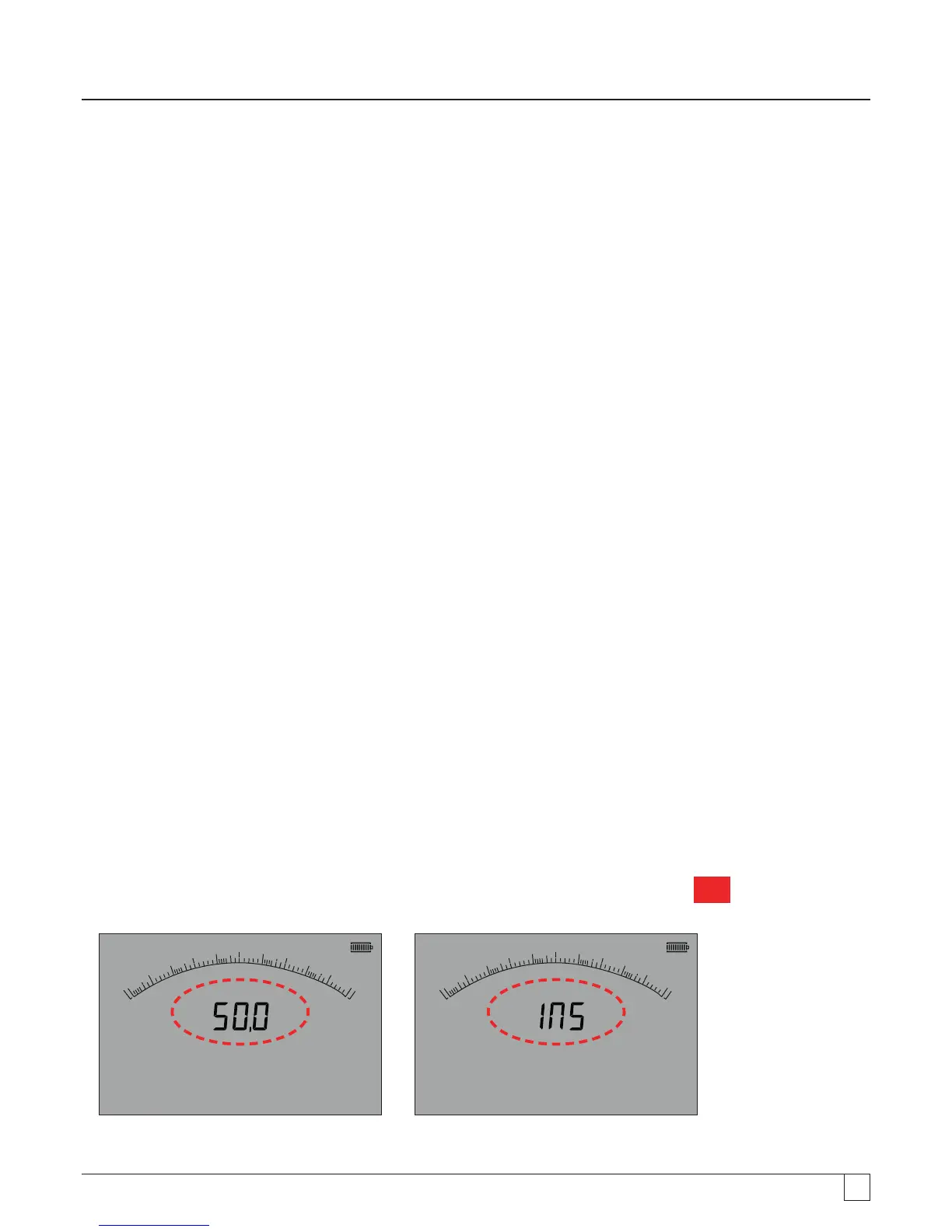
If a voltage below 50 V appears on the circuit under test the instrument will complete a measurement.
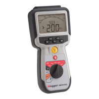
On circuit voltages over 50 V the instrument will sound a warning buzzer and display the circuit voltage on test ranges that are not
designed to measure voltage, such as the insulation test. The instrument will be prevented from performing an insulation test. See
section 13 - SETUP
Note: The test disable limit is increased on MIT481/2 and MIT485/2 to 75 V, but a warning buzzer will indicate voltages
above 30 V.
Use extreme care when using or measuring voltages above 30 V, particularly in high energy systems.
Fused test leads are available as an optional accessory for local situations where increased protection is required. See section 13 -
SETUP
Hazardous voltages can exist on the insulation test range all the time the [TEST] button is locked down.
9.1 Measurement for 2 terminal instruments and MIT2500
Note: For all insulation tests up to 1000 V, the RED test lead can be replaced by the SP5 switched test probe.
The SP5 switch probe button operates the test functions in exactly the same way as the TEST button on the instrument, but without
having to look away from the equipment being tested.
9.1.1 Insulation testing
1. Connect test leads to the RED / BLACK test sockets on the instrument.
2. Select one of the test voltages on the insulation (MW) measurement mode using the range knob [
MW
]. The Instrument will
display the range voltage selected in the display as below:
G
0
0.01
0.1
110
100
W
8
W
M
V
G
0
0.01
0.1
110
100
W
8
W
M
- Figure 17 MIT420/2 and MIT430/2 -Figure 17a MIT400/2 and MIT410/2
3. Connect the test leads to the circuit to be measured.