Transformer Testing
AVTMTO210 Rev 7 Sept 2013
27
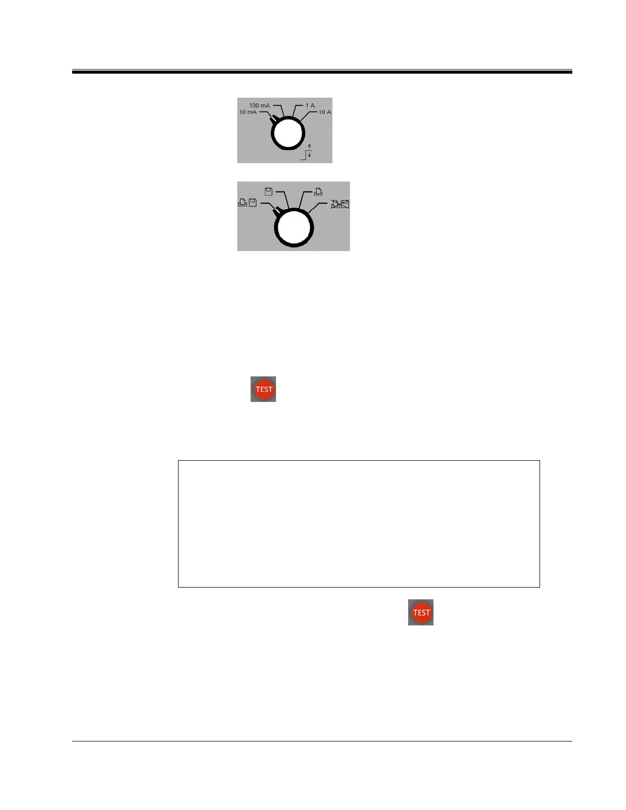
b.
Set to desired MAXIMUM TEST
CURRENT.
c.
Set to desired DATA OUTPUT.
4. Connect "V1" voltage leads to test specimen winding. Do not clip
potential leads on the current leads, since this will add contact resistance
to the measurement. See Figure 2.
Connect current output (I) to test specimen winding. See Figure 2.
5. Turn power switch "ON" (-).
6. Press button to initiate current flow.
7. The top smaller display indicates current output and the Ohm1 display
indicates resistance of specimen.
NOTE For larger transformers, the resistance display should be observed and
resistance readings taken when the reading stabilizes. The drift in the
indicated resistance reading is due to the inductance of the transformer.
For small transformers the drift lasts for only a few seconds; for single-
phase high voltage transformers (500kV), the drift may last for a
fraction of a minute; for large delta connected transformers the settling
time may be much longer, see section “Testing Delta Connected
Windings”. A 345MVA, 500kV single-phase transformer requires
approximately 2 minutes for the display to settle.
8. When measurement is complete, press to terminate measurement
and discharge current. Discharge is complete when the discharge
indicator is off.
9. Remove the current leads from the transformer.
10. Remove the potential leads form the transformer.