M
AVTMMTO210 Rev 7 Sept 2013
32
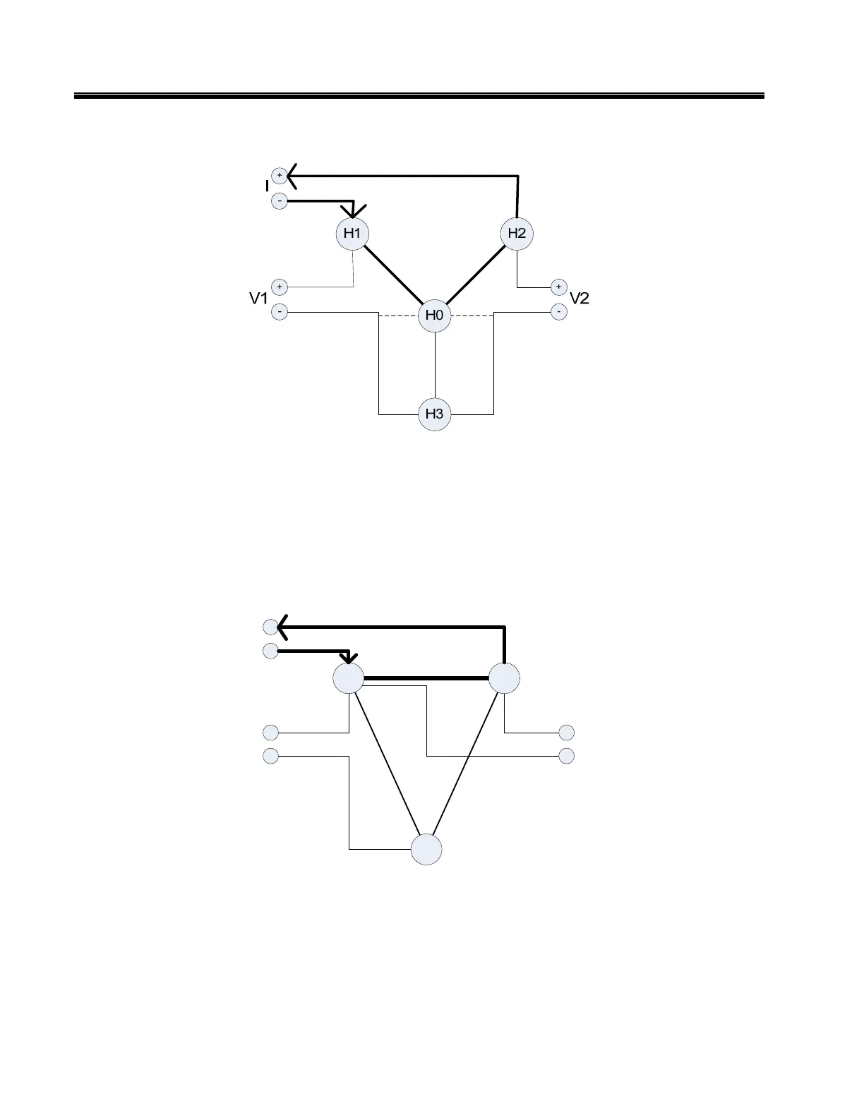
2. Three-Phase Wye Configured Winding, No Neutral Brought Out
Figure 5: Reading obtained is between pairs of terminals, Resistance of A and B Windings
Use the above diagram in conjunction with procedure "Single-Phase
Transformer Test".
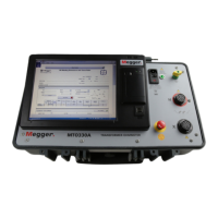
3. Three-Phase, Delta Configured Winding
Figure 6: Reading is between pairs of terminals. Resistance of A in parallel with B+C Windings
Use the diagram in Figure 6 in conjunction with procedure "Single-Phase
Transformer Test".
X3
X1 X2
+
-
I
+
-
V1
+
-
V2