www.megger.com
2
Contents
Unpacking the carton 3
Safety warnings 4
Symbols used on the instrument 5
Symbols used on the connection panel 6
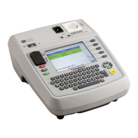
Instrument layout 6
PAT120 and display information
6
Measurement symbols
7
Instrument buttons
7
User guide INSTRUCTION symbols
8
Carry strap fitting and removal 9
Switching ON / OFF 10
Class I test
(PAT120) using substitute leakage @ 40 V ac
11
Class II test
(PAT120) Using Substitute Leakage @ 40 V ac
12
Power cord test
(PAT120)
13
Extension lead test
(PAT120)
14
Fail handling 15
Factory reset to default settings 16
International model variations 16
Battery and fuse replacement (PAT120, 150) 17
Battery replacement
17
Fuse replacement
18
Preventive maintenance 18
Specification 18
 Loading...