15
Notes on encoder wiring
The encoder (PG) signal cable should be kept away from the cables of main circuits and power cables and
parallel cabling with narrow clearance shall not be adopted for such cables. The PG cable shall adopt
shielded cable, and the shielding layer shall be connected to the PE terminal at the location close to the drive
side.
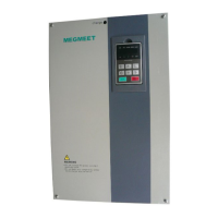
1. When the PG output signal is open collector signal, the wiring with the interface board terminal is as shown
in Fig. 2-4:
Fig. 2-4 Schematic diagram for wiring of PG with open collector signal
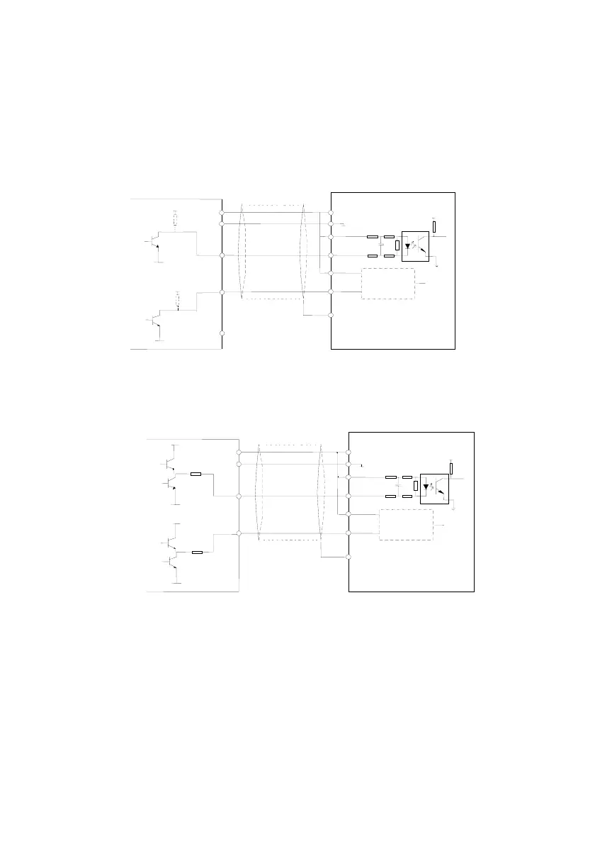
2. When the PG output signal is push-pull signal, the wiring with the interface board terminal is as shown in
Fig.2-5:
Fig. 2-5 Schematic diagram for wiring of PG with push-pull signal
3. When the PG output signal is differential signal, the wiring with the interface board terminal is as shown in
Fig.2-6:
0V
MV600L
VCC
0V
B
+3.3V
12C
PE
COM
+
-
B-
B+
B
VCC
VCC
Shield cable
The same as A
0V
Shield single-end
grounded near drive
0V
MV600L
VCC
0 V
B
12C
PE
COM
+
-
B-
B+
B
Shield cable
Shield single-end
grounded near drive
The same as A
0V
VCC
VCC
+3.3V
 Loading...