EasyManua.ls Logo

Megmeet MV300 Series - User Manual

Default Icon
262 pages
To Next Page IconTo Next Page
Loading...
1
MV300 Series Universal Vector Control Variable
Speed Drive
User Manual
Document Version: V1.0
Archive Date: 2015/07/29
BOM Code: R33010207
Shenzhen Megmeet Drive Technology Co., Ltd. provides full technical support for our
customers. Customers can contact local Megmeet offices or customer services centers, or
directly contact Megmeet headquarters.
Shenzhen Megmeet Drive Technology Co., Ltd.
All rights reserved. The contents in this document are subject to change without notice.
Shenzhen Megmeet Drive Technology Co., Ltd.
Address: 5th Floor, Block B, Unisplendor Information Harbor, Langshan Rd., Science &
Technology Park, Nanshan District, Shenzhen, 518057, China
Website: www.megmeet-drivetech.com
Tel: +86-755-86600500
Fax: +86-755-86600562
Service email: driveservice@megmeet.com

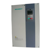
Table of Contents

Questions and Answers:

Megmeet MV300 Series Specifications

General IconGeneral
Ambient Temperature-10°C to +40°C (derating above 40°C)
Storage Temperature-20°C to +60°C
AltitudeUp to 1000m (derating above 1000m)
Output Voltage0 ~ Input Voltage
Control ModeV/F control
ProtectionOvercurrent, Overvoltage, Undervoltage, Overload, Overtemperature, Phase Loss, Short Circuit
CommunicationRS485, Modbus RTU
Humidity5% to 95% RH, non-condensing

Summary

Foreword and Unpacking Precautions

Precautions for Unpacking Inspection

Guidelines for checking the product upon unpacking for damage and specification consistency.

Safety Precautions for MV300 Drive

Introduction to MV300 Series Drive

Product Model Description

Explanation of the drive model designation, including series, voltage, power, and codes.

Product Nameplate Details

Information presented on the MV300 drive's nameplate.

MV300 Product Series Specifications

Table listing MV300G and MV300P product models with capacity, current, and power ratings.

Technical Specifications of MV300 Drive

Detailed technical specifications covering input/output power, features, environment, and performance.

MV300 Drive Structure and Dimensions

Diagram of drive structure and outlines/mounting dimensions for various drive enclosures.

Operation Panel and Box Dimensions

Physical dimensions and mounting details for the drive's operation panel and its enclosure box.

Drive Options and Braking Components

Overview of available options like LCD panels and details on braking components.

Drive Installation Procedures

Removal and Installation of Drive Components

Step-by-step guide for safely removing and installing covers, operation panel, and other components.

Installation Environment Requirements

Conditions to consider for selecting the installation environment, including temperature, humidity, and vibration.

Mounting Direction and Spacing Guidelines

Recommendations for drive mounting orientation and required clearances for proper ventilation.

Wiring the MV300 Drive

Safety Precautions for Drive Wiring

Essential safety warnings and checks before and during drive wiring procedures.

Main Circuit Terminal Configuration

Detailed descriptions of main circuit input/output terminals and their functions for different models.

Connecting Drive and Optional Components

Illustrations and guidelines for connecting the drive with external options like reactors and filters.

DC, AC Input;Output Reactors, and EMI Filters

Guidance on configuring reactors and EMI filters for power quality and noise suppression.

Safe Grounding Wire Requirements

Specifications and importance of proper grounding for safety and interference reduction.

Basic Wiring Diagrams for Drive Operation

Illustrative diagrams showing common wiring configurations for basic drive operation.

Control Circuit Wiring and Terminal Functions

Detailed explanation of control circuit terminal arrangement, functions, and wiring.

Analog Input;Output Terminal Wiring

Wiring procedures for analog input (AI1, AI2) and analog output (AO1) terminals.

Communication Interface Wiring

Instructions for establishing communication via RS485 interface and connecting to host devices.

Digital Input;Output Terminal Wiring

Wiring configurations for digital input terminals in Dry Contact and Source/Drain modes.

Wiring for Multi-functional Output Terminals

Wiring examples for multi-functional output terminals (Y1, Y2) using internal or external power.

EMC Installation and Noise Suppression

Schematic Diagram of Control Board

Diagram illustrating the layout and connections of components on the drive's control board.

Installation Methods for EMC Requirements

Guidelines for installation to reduce electromagnetic interference and meet EMC standards.

Noise Suppression Techniques

Methods for classifying noise and strategies to reduce its transmission and impact.

Field Wiring Requirements for Interference Reduction

Guidelines for routing cables to minimize interference coupling between different types of wiring.

Proper Grounding Methods

Recommended grounding diagrams and best practices for ensuring safety and signal integrity.

Installation Requirements for Noise-Generating Components

Installation guidelines for external components like relays and contactors that generate noise.

Leakage Current and Countermeasures

Explanation of leakage current paths and methods for its suppression.

Drive EMC Installation Partitioning

Principles of partitioning the drive system into EMC zones for effective noise isolation.

Drive Electrical Installation Diagram

Overall diagram showing the electrical installation layout, including component placement and clearances.

Power Filter Installation Instructions

Guidance on power filter installation, common errors, and its role in EMC compliance.

Drive Radiation Emission Suppression

Discussion on drive radiation emission and methods to suppress it through proper cabling.

Quick Operation Guide for MV300 Drive

MV300 Drive Operation Panel Overview

Introduction to the operation panel, including LED indicators and key functions.

LED Display Symbol Identification

Mapping of LED display symbols to characters and figures shown on the panel.

Operation Panel Key Functions

Detailed description of each key's function on the operation panel for user interaction.

Operation Panel Status Display

Explanation of different status displays on the operation panel: stop, run, alarm, and fault.

Function Code Editing and Password Operations

Procedure for editing function codes and managing the password protection feature.

Key Locking and Unlocking Functionality

Steps to lock and unlock the operation panel keys to prevent unintended access.

Operation Panel Self-Detection Procedure

Guide to performing a self-test of the operation panel's components and functions.

Restoring Factory Default Parameters

Instructions on how to reset drive parameters back to their factory default values.

Setting the Drives Operating Frequency

Procedure for setting the desired operating frequency for the drive using function codes.

Switching Status Display Parameters

How to configure and view different status parameters displayed on the operation panel.

MV300 Drive Running Modes

Explanation of different drive running modes and command channels.

Drive Control and Running Mode Settings

Details on control modes (Vector, V/F) and running modes supported by the MV300 drive.

Drive Frequency and Torque Channels

Description of channels used for frequency and torque references in different modes.

Initial Drive Power-Up Procedure

Steps and checks required for the initial power-up and startup of the drive.

MV300 Parameter Description

System Management Parameters (Group P00)

Configuration of system-level parameters including menu modes, password, and language.

Status Display Parameters (Group P01)

Parameters for monitoring drive status like frequency, current, voltage, and fault records.

Basic Drive Parameters (Group P02)

Essential parameters for drive operation, including control mode, frequency sources, and direction.

Motor Parameters (Group P03)

Configuration of motor characteristics (power, voltage, speed, factor) for optimal performance.

Speed Control Parameters (Group P05)

Parameters for tuning the speed control loop (PI parameters) for precise motor speed regulation.

Torque Control Parameters (Group P06)

Configuration of torque control mode, limits, and compensation parameters.

VF Control Parameters (Group P07)

Parameters for setting Voltage/Frequency (V/F) control curves for motor 1 and motor 2.

Start and Stop Control Parameters (Group P08)

Parameters governing drive start-up modes, stop modes, and fault restart behavior.

Digital Input;Output Parameters (Group P09)

Configuration of digital input and output terminals for various control functions.

Analog Input;Output Terminal Parameters (Group P10)

Configuration of analog input (AI1, AI2) and output (AO1) terminals for various signals.

Auxiliary Function Parameters (Group P11)

Parameters for auxiliary functions like acceleration/deceleration time unit and curves.

Advanced Function Parameters (Group P12)

Parameters for advanced functions like energy saving, carrier frequency, and PWM optimization.

Multi-stage Reference and Simple PLC Parameters (Group P13)

Parameters for setting up multi-stage references and simple PLC functions for automated control.

Process PID Parameters (Group P14)

Parameters for configuring the Proportional-Integral-Derivative (PID) control loop for precise process regulation.

Communication Parameters (Group P15)

Settings for serial communication port, including Modbus protocol, baud rate, and data format.

Fieldbus Option Parameters (Group P40)

Parameters for configuring fieldbus communication options like Profibus-DP.

Protection and Fault Parameters (Group P97)

Settings for various protection mechanisms, fault handling actions, and alarm types.

Drive Parameters (Group P98)

Parameters related to drive identification, software versions, and series selection.

Troubleshooting Common Issues

Displaying Exceptions and Solutions

Table of possible fault codes, their causes, and recommended solutions for troubleshooting.

Resolving Operation Exceptions

Common operational problems with the drive and their corresponding solutions.

Drive Maintenance Procedures

Daily Maintenance Inspections

Daily checklist and procedures for routine checks of the drive and its operating environment.

Periodical Maintenance Schedule and Tasks

Recommended schedule and detailed inspection steps for periodic maintenance.

Replacing Drive Wearing Parts

Guidance on identifying and replacing common wear components like fans and capacitors.

Proper Drive Storage Instructions

Guidelines for temporary and long-term storage of the drive to prevent degradation.

Modbus Communication Protocol Details

Networking and Interface Modes

Description of networking modes and RS485 interface specifications.

Modbus Communication Protocol Functions

Overview of Modbus command codes for reading and writing drive parameters.

Modbus Protocol Data Unit Formats

Details on Modbus RTU and ASCII frame formats, including command and data structures.

CRC Verification and Calculation

Explanation and C source code for CRC-16 checksum calculation used in Modbus communication.

Application Examples of Modbus Commands

Practical examples demonstrating Modbus commands for drive operations like start, stop, and jog.

Parameter Access Modes and Data Types

Explanation of 16-bit and 32-bit access modes for drive parameters and data handling.

Modbus Command Cautions

Important cautions regarding Modbus commands for continuous parameter writing and error handling.

Modbus Parameter Save Behavior

Information on which parameters are saved after power off based on command codes.

Braking Components for MV300 Drive

External Braking Unit Model Definition

Explanation of the model designation for external braking units and utilization rate.

External Brake Module Configuration Guide

Table detailing external brake module configurations based on motor power and braking torque.

Built-in Brake Unit Drive Resistor Configuration

Recommended brake resistor specifications for drives with built-in brake units.

Braking Unit Wiring and Usage

Wiring instructions for built-in and external braking units, including connection diagrams.

Brake Unit Functions

Details on brake unit functions like voltage adjustment, overheat protection, and fault indication.

Warranty and Service Information

Product Warranty Period and Scope

Details on the warranty duration, coverage, and conditions for repairs or replacements.

After-Sales Service Contact and Procedures

Information on contacting customer support for installation, troubleshooting, and repair services.

Drive Wiring Diagram

Related product manuals