61
Fig. 4-7 Operation example for setting the set frequency
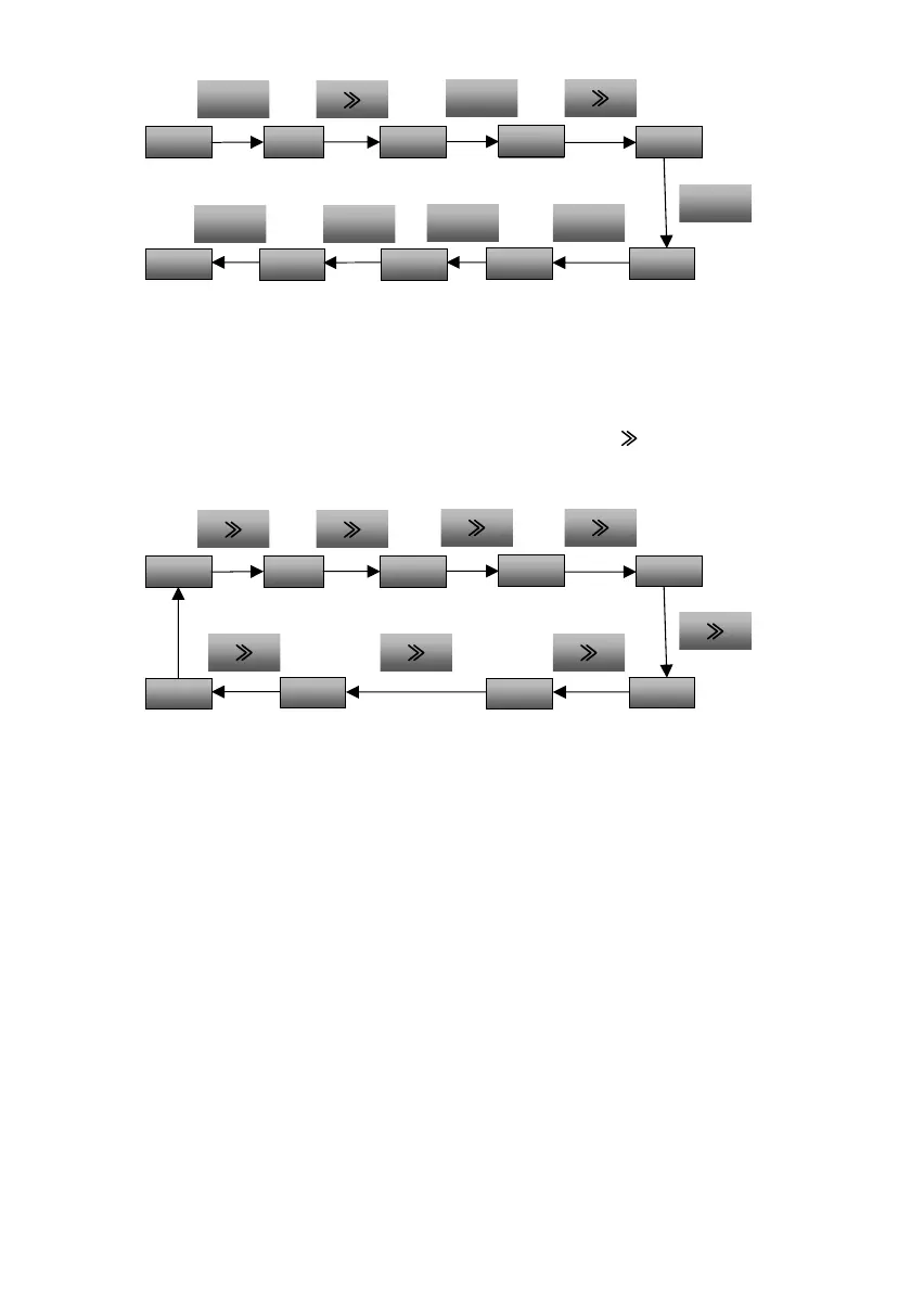
4.1.3.6 Switching status display parameters
The drive parameters displayed on the operation panel when the drive is stopped can be set through function
code P16.02, such as the frequency, bus voltage, etc. (For details, please refer to the description of function
codes of Group P16). These status parameters can be viewed by pressing the
key on the operation
panel when they have been set. The example for the status parameter display in the drive stop status when
P16.02 is FFF is as shown in Fig.4-8.
Fig. 4-8 Operation example for switching status parameter display
4.2 Drive running mode
The terms describing the drive control, running and status will appear in the following chapters. Please read
carefully this chapter. It will help you understand and properly use the functions described in the following
chapters.
4.2.1 Drive running command channel
The drive running command channel refers to the physical channel for the drive to receive the running
command: start, stop, jog, etc. There are four types of running command channels:
1. Operation panel: To control through the RUN, STOP and M (when set as the JOG function) keys on the
operation panel.
2. Control terminal: To control through the control terminals X1, X2 (default, other digital input terminals
can be set as FWD and REV input control terminals as well), COM (two-wire system) and Xi (three-wire
system).
3. Serial port: To control the start and stop through the host device.
4. Field bus: To control the start and stop through the field bus (Profibus-DP, CanOpen, etc.).
50.00 0.0 1500.0
0.50
540
0.00
0.0
0.00
0.00
50.00 P00.00 P00.00
P02.0550.00
>
MENU
ESC
MENU
ESC
ENTER
DATA
>
P02.00
P02.00
25.00
>
P00.06
25.00
ENTER
DATA
 Loading...