179
105
10
0
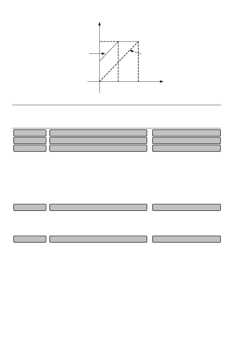
P10.25 = 0%
Value before adjustment(
V
)
Value after adjustment
(
V
)
P10.25 = 50%
Fig. 6-50 Relation curve between analog output and zero offset
Note
The output gain and zero offset correction function codes will real time affect the analog output during the
change.
P10.29 and P10.30 are used for correcting the zero offset of analog inputs AI1 and AI2.
Take AI1as an example to introduce zero offset correction.
AI1 is used as voltage type signal, when the input signal is 0V, observe AI1 value P01.20, if P01.20 is
non-zero value at this time, it indicates that AI1 has zero offset, you need to enter the value which has
equal absolute value but opposite sign with P01.20 in P10.29. If P01.20 = 0.01V, then set P10.29 =
-0.01V.
6.11 Auxiliary function parameters (Group P11)
0: Linear acceleration/deceleration
The output frequency is decreased or increased according to constant slope, as shown in Fig. 6-51.
Acceleration/deceleration mode selection 0~1
0
P11.00
Reserved 0P10.31
AI2 zero offset correction -1.00~1.00
0.00V
P10.30
AI1 zero offset correction -1.00~1.00
0.00V
P10.29
Reserved 0P10.26~P10.28
 Loading...