45
When the input signal of the emergency stop terminal (NO. 60 terminal function) is enabled, the drive
begins to decelerate to stop. The deceleration time is determined by P08.23. When it is set as 0s, the
drive will stop within the shortest deceleration time.
4.5 Auxiliary function parameters (Group P11)
The acceleration time means the time needed for the drive to accelerate from 0Hz to the maximum output
frequency (P02.15). The deceleration time means the time needed for the drive to decelerate from the
maximum output frequency (P02.15) to 0Hz.
MV600L series drive has four acceleration/deceleration time settings in total. The acceleration/
deceleration time (1~4) of the drive in the operation can be selected by different combinations of control
terminals. Please refer to the definition on functions of the acceleration/deceleration time terminal in
P09.00~P09.07. They can be also defined as the acceleration/deceleration time for the running
frequency switch between various stages when the drive is running in the simple PLC mode. Please refer
to the description in group P13 parameter.
Note
The time unit (minute, second) of the acceleration/deceleration time 1~4 can be selected via P11.01 and the
default leave-factory unit is second.
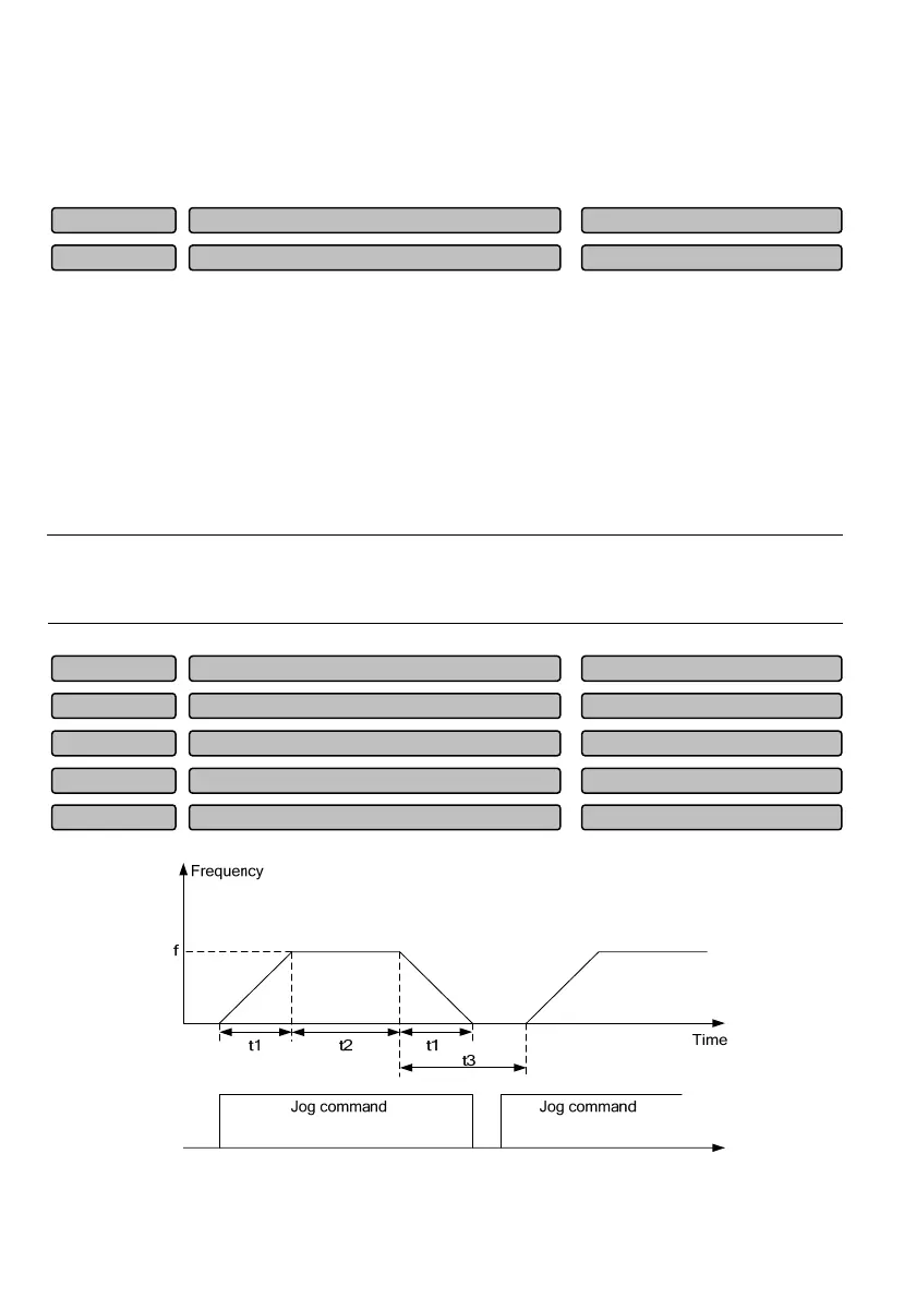
Fig. 4-1 Description of the jog running parameter
Jo
runnin
fre
uenc
0.10~50.00 Hz (5.00 Hz)
P11.18
Jo
interval time
0.0~100.0s (0.0s)
P11.17
Jo
acceleration/deceleration time
0.1~60.0s (6.0s)
P11.16
Switching hysteresis loop frequency of Acc/Dec time 1 and 2
0.00~655.35Hz (1.00 Hz)
P11.15
Switchin
fre
uenc
of Acc
Dec time 1 and 2
0.00~3000.00Hz (0.00 Hz)
P11.14
Deceleration time 2
0.0~3600.0 (6.00)
P11.03
Acceleration time 2
0.0~3600.0 (6.00)
P11.02
 Loading...