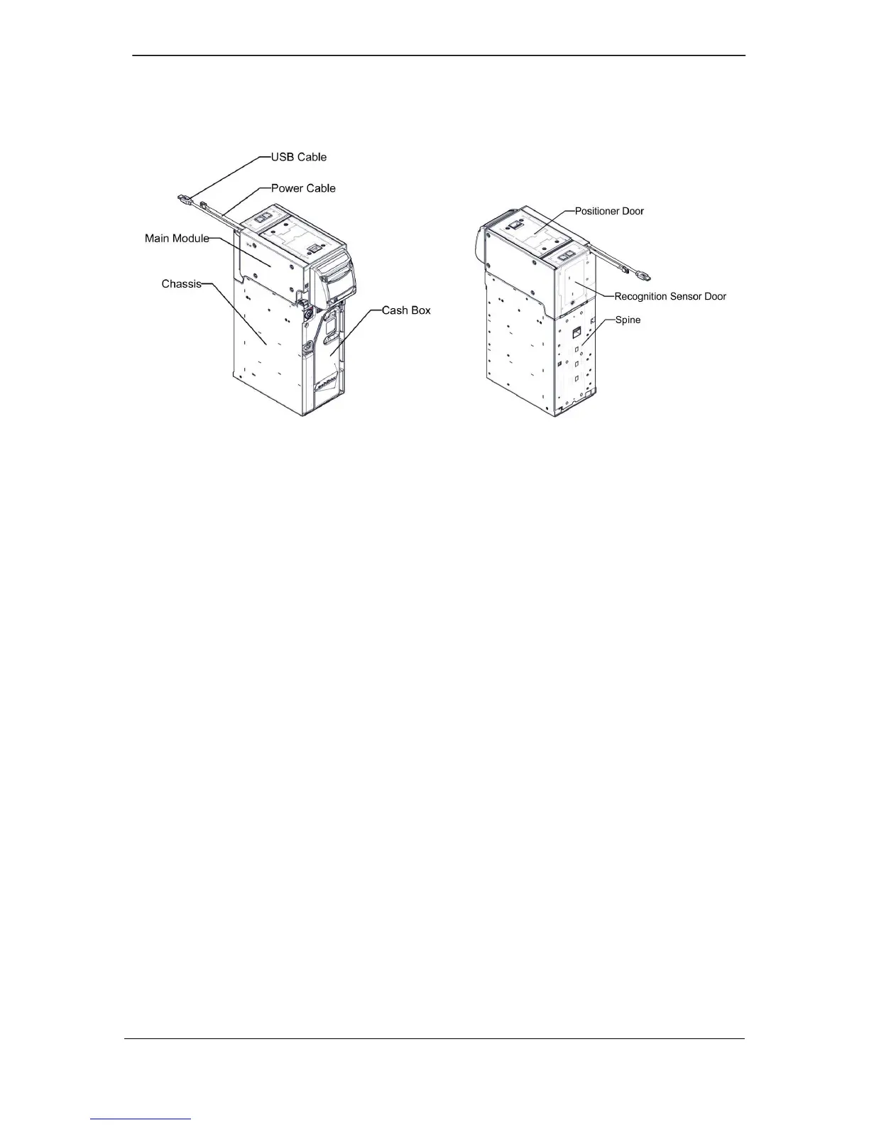
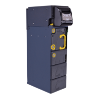
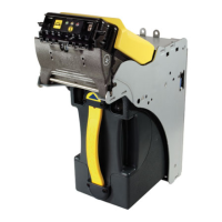
Example of a BNA6-L
The required conditions for normal operations of the BNR/BNA6 are:
Power cable and USB cable correctly connected,
Positioner door, Recognition Sensor door and Spine door correctly closed,
The Main Module correctly connected to the Spine (refer to “INSTALL THE
MAIN MODULE ONTO THE CHASSIS” in the BNR&BNA6 Service Manual),
Each module correctly inserted,
Interlock System correctly locked (refer to “LOCKS AND SECURITY
PRINCIPLE” in the “NORMAL OPERATIONS IN HOST MACHINE” chapter),
The green unlocking lever is inserted completely,
BNR/BNA6 Chassis properly linked to the local ground,
BNR/BNA6 and Host machine are powered up and BNR/BNA6 is reset.