MEITRACK T711L GPS Vehicle Tracker User Guide
Copyright © Meitrack Group 2021. All rights reserved. - 16 -
For details, see the MEITRACK MS03 GPS Tracking System User Guide.
8 Device Installation
8.1 Installing the I/O Port Cable
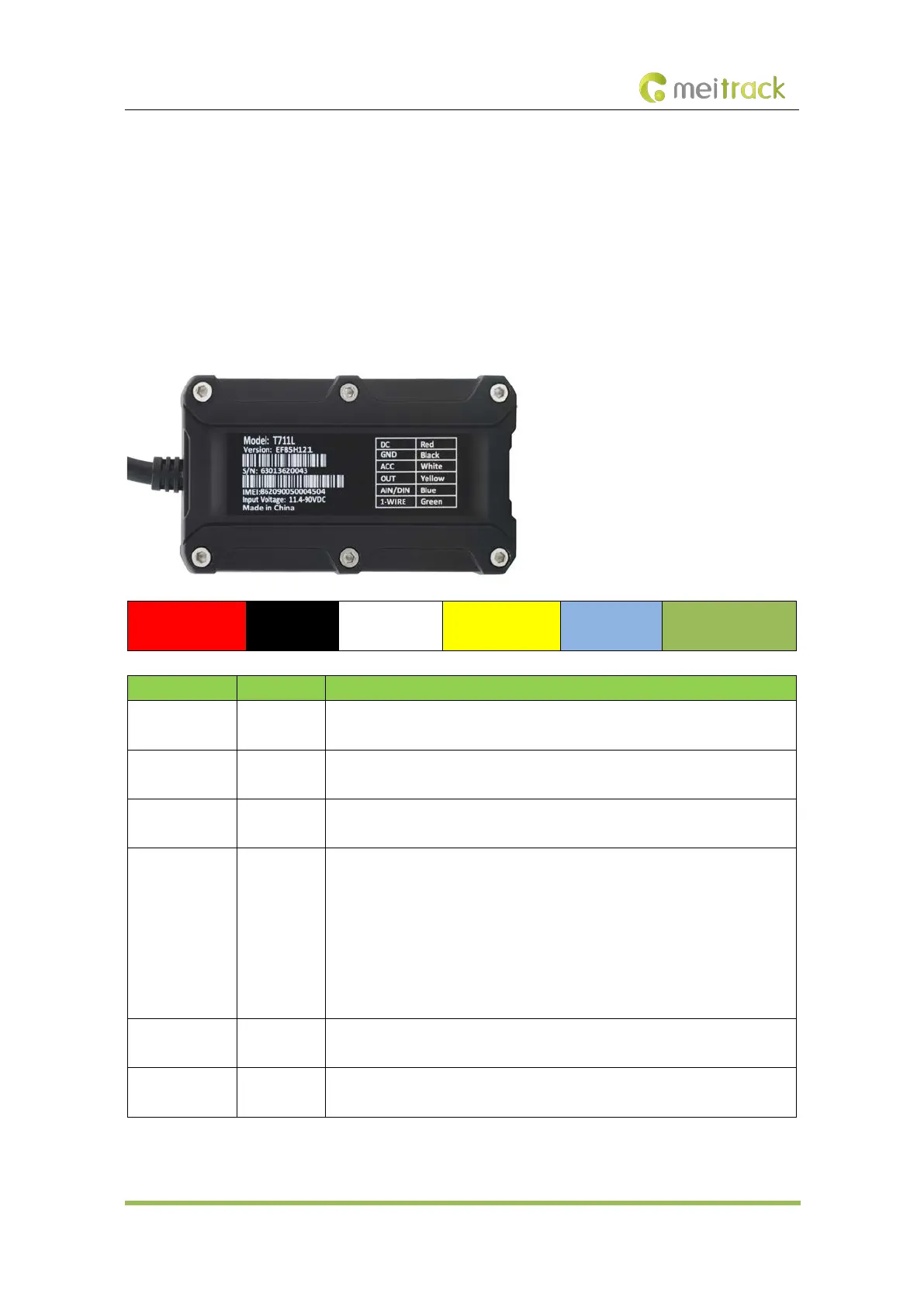
8.1.1 Interface Definition
The I/O port cable of the device is a 6-pin cable, including the power port, analog input port, positive input port, negative
input port, output port, and 1-Wire port.
1
Power (+)
2
GND (-)
3
Input 1 (+)
4
Output 1
5
Analog input 1
6
1-Wire port
Pin Number Cable Color Description
1 (Power +) Red Positive charge of the power input. Connect to the positive charge of the vehicle
battery. Input voltage: 11.4–90 V. 12 V or 24 V is recommended.
2 (GND) Black Ground wire. Connect to the negative charge of the vehicle battery or to the
negative terminal.
3 (Input 1) White Digital input (positive trigger). The port can be configured as the negative trigger.
Connect to the vehicle's ACC cable by default to detect the vehicle's ACC status.
4 (Output 1) Yellow Valid: low level (0 V)
Invalid: open collector
Maximum voltage for the open collector output (invalid): 60 V
Maximum current for the low level output (valid): 500 mA
Set the PWM output (adjustable output time and pulse width).
Connect to an external relay to remotely cut off the vehicle fuel cable or engine
power supply.
5 (Analog input
1)
Blue Analog input with 12-bit resolution. Valid voltage: 0–30 V.
The port can be configured as negative input 2.
6 (1-Wire port) Green Connect to the iButton reader and other devices supporting the 1-Wire protocol.
The port can be configured as negative input 3 or open collector output 2.
 Loading...