85-03-01109 FV42 Page 24
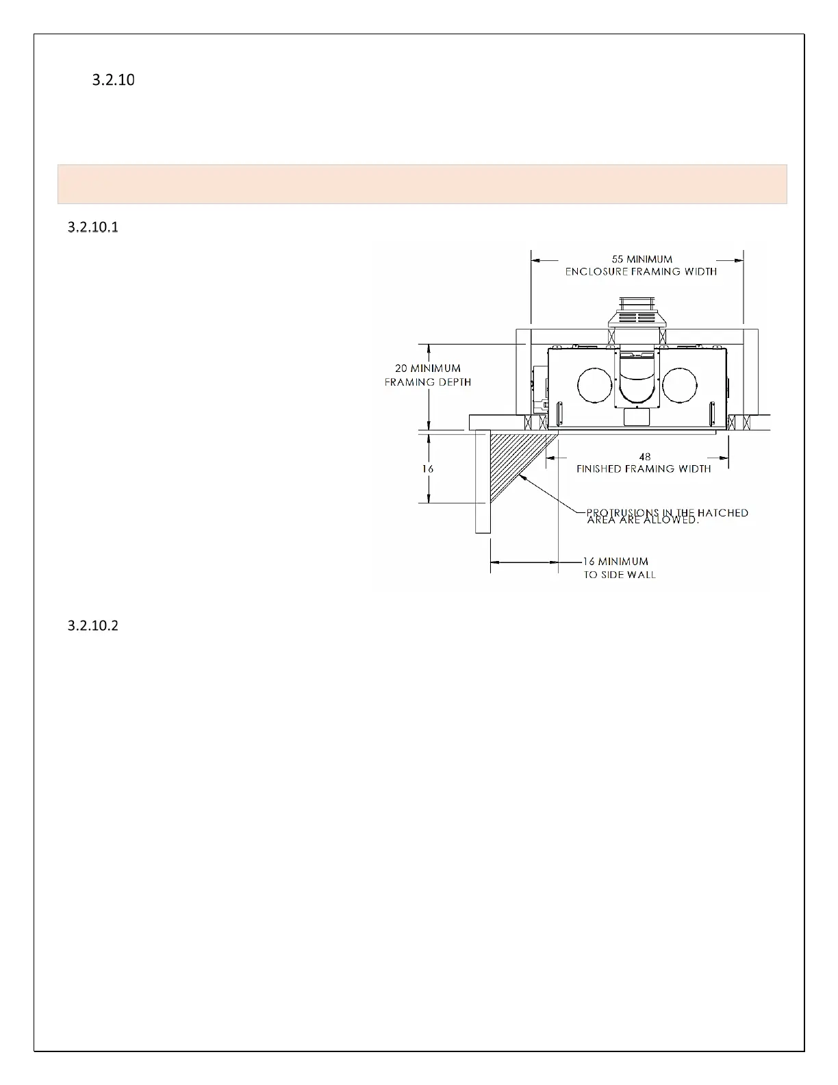
Clearances to Combustible Side Walls
The minimum distance required from the side edge of the visible glass to a combustible side wall is 16”. Combustible side walls,
mantel corbels, mantel legs and other combustible walls and decorative objects must fall behind a 45-degree line extending
outward from the side edges of the visible glass unless such objects are more than 16” away from the visible side edges of the
glass. See Figure 3-19 Side Wall Clearances.
If the required clearance cannot be met to a pre-existing combustible side wall, an NFPA approved clearance
reduction shield, metal or ceramic board, must be added to the side wall.
Horizontal Clearance Reduction by 66%
NPFA 211 Approved: Install 20-gauge or heavier
steel shield that provides at least a 1” active
airspace, on the combustible wall surface. To
provide for active airflow, install at least 1” metal
or ceramic standoffs or spacers between the
metal shield and the combustible surface being
protected. The bottom and top edges of the
cavity between the metal shield and the
combustible surface must be left open. The steel
shield must be a minimum of 12” larger in each
direction than the surface area of the source of
heat; or if the surface being protected is smaller
than surface area of the source of heat, this
shield must be larger than the combustible
surface in each direction.
By using this method of protection, if the
required horizontal clearance was 16”, the
resulting clearance will be reduced by 66% to 5-
3/8” between the heat source and the metal
shield.
Horizontal Clearance Reduction by 50%
NPFA 211 Approved: Install an R-1 rated ceramic board or R-1 rated mineral board on the wall you are attempting to protect.
by using this method of protection, if the required horizontal clearance was 16”, the resulting clearance will be reduced by 50%
to 8” between the heat source and the R-1 Rated wall board.
Figure 3-19 Side Wall Clearances