Page 18 of 24
6. Use of multiple pumps
Up to three pumps can be connected
providing the following benefits:
• Higher throughput
• Use of single power supply
• Daisy chain start: up to six samples
filtered with a single push of a button
6.1 Material needed
6.1.1 Two pumps connected:
• Two Milliflex Oasis
®
pumps for EZ-Fit
®
filtration unit (item MMSYSTEZ1)
• Milliflex Oasis
®
electrical cable
for connecting two pumps
(item MMCABLEMM)
• Milliflex Oasis
®
power supply, the item
number is specific to defined regions:
- Australia: item MMPWRSPAU
- Brazil: item MMPWRSPBR
- China: item MMPWRSPCN
- Denmark: item MMPWRSPDK
- Europe: item MMPWRSPEU
- Switzerland: item MMPWRSPSZ
- India: item MMPWRSPIN
- UK: item MMPWRSPUK
- Japan: item MMPWRSPJP
- South Africa: item MMPWRSPZA
Optional: Milliflex Oasis
®
T connectors for
tubing (item MMTCNNECT)
6.1.2 Three pumps connected:
• Three Milliflex Oasis
®
pumps for EZ-Fit
®
filtration unit (item MMSYSTEZ1)
• Two Milliflex Oasis
®
electrical cables
for connecting two pumps (item
MMCABLEMM)
• Milliflex Oasis
®
power supply, the item
number is specific to defined regions
Optional: Milliflex Oasis
®
T connectors for
tubing (item MMTCNNECT)
6.2 Installation
The pumps must be installed on a level
surface to ensure good sample volume
readings.
• Take the pump bodies and the tubing
out of the package with care
• Take out the accessory bags
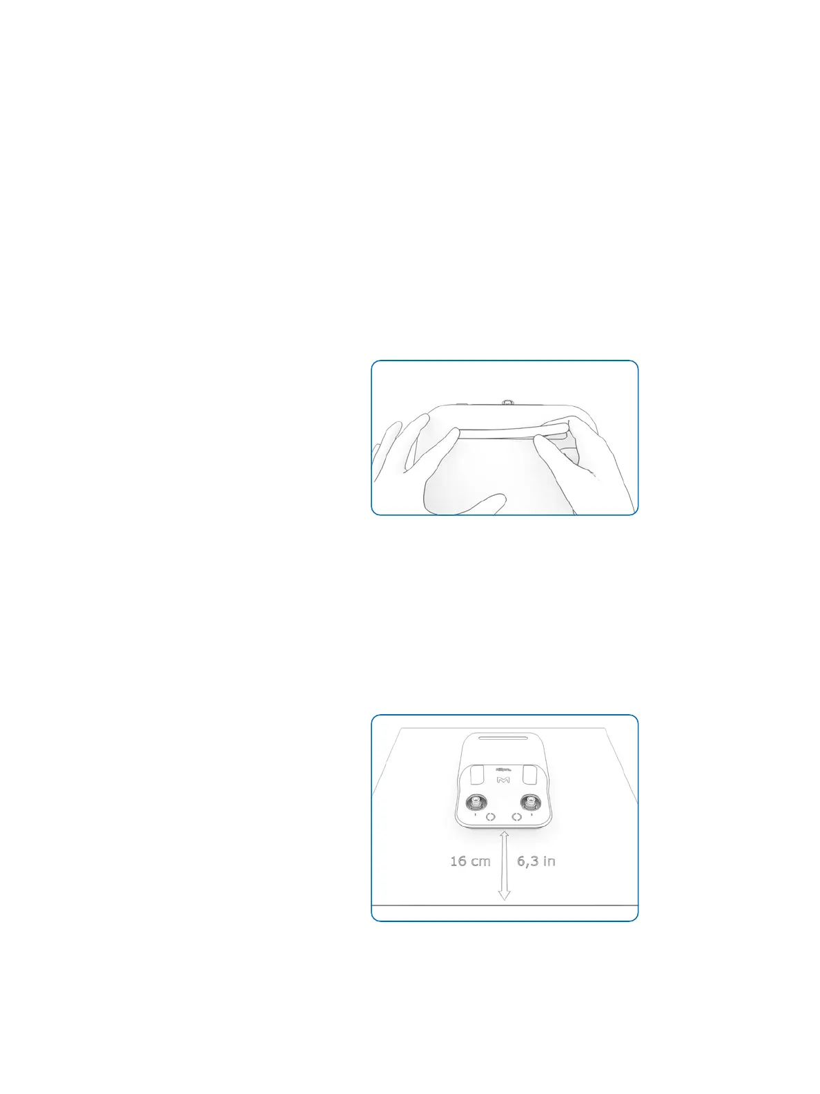
Optional: the accessory bag contains four
stickers, select your preferred sticker and
stick it carefully to the specific groove on
each pump.
Figure 30: Pump sticker set up
• Clean the exterior of the pumps and
the tubing using a wipe moistened with
a surface sanitizer listed in the cleaning
& maintenance section
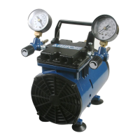
• Place the pumps in the working area
Under a horizontal laminar flow hood, the
front of the pumps must be placed at least
at 160 mm (6.3 in.) from the front edge of
the LFH (see picture).
Figure 31: The front of the pump must be placed
at least at 160 mm (6.3 in.) from the front edge
of a horizontal LFH


 To Next Page