If the resistance is not as indicated, inspect the sensor wiring and connections.
Trim Switches and Sensor ‑ DTS
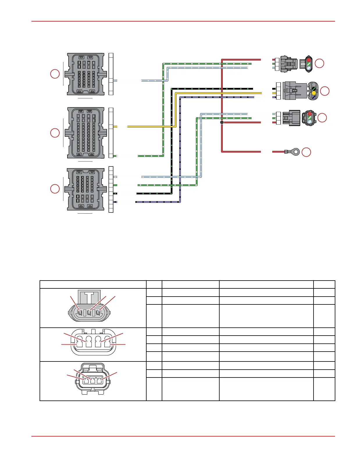
a - PCM connector A
b - PCM connector B
c - PCM connector C
d - Trim harness connector
e - Trim position sensor connector
f - Cowl tilt switch connector
g - Hot stud (battery +)
Connector Pin Wire Color Function PCM
A Red 12 V battery power (+) –
B Green/white Trim down relay control BM4
C Light blue/white Trim up relay control AA3
1 N/A Not used –
2 Black/green Sensor ground C (–) CE3
3 Yellow Trim position sensor signal BC2
4 Purple/black Sensor power C (+) CE4
1 Red 12 V battery power (+) –
2 Green/white Trim down (from switch) CC3
3 Light blue/white Trim up (from switch) CC2
S109B
GRN/WHT
YEL
PPL/BLK
BLK/GRN
LT BLU/WHT
GRN/WHT
RED
LT BLU/WHT
LT BLU/WHT
GRN/WHT
GRN/WHT
RED
RED
YEL
PPL/BLK
BLK/GRN
LT BLU/WHT
3
2
1
H4
C2
C3
E3
E4
A1
C2
M4
A1
A1
A3
H4
2
3
4
1
A
B
C
A B
C
D E F G H
J
K
AB
C
DEFGH
J
K
1
3
2
4
L
M
L
M
Conventional Midsection (CMS) Power Trim
90-8M0146617 eng JULY 2018 © 2018 Mercury Marine Page 6C-15
 Loading...