Checking LED Activity
© 2010 Meru Networks, Inc. Installing AP150 83
10. For each antenna, loosen the knurled ring at the base of the antenna (see
Figure 28), point the antenna straight down, then retighten the ring.
11. Connect one end of the PoE 100BaseT Ethernet cable to the 100/1000 Ethernet
connector, shown in (see Figure 29).
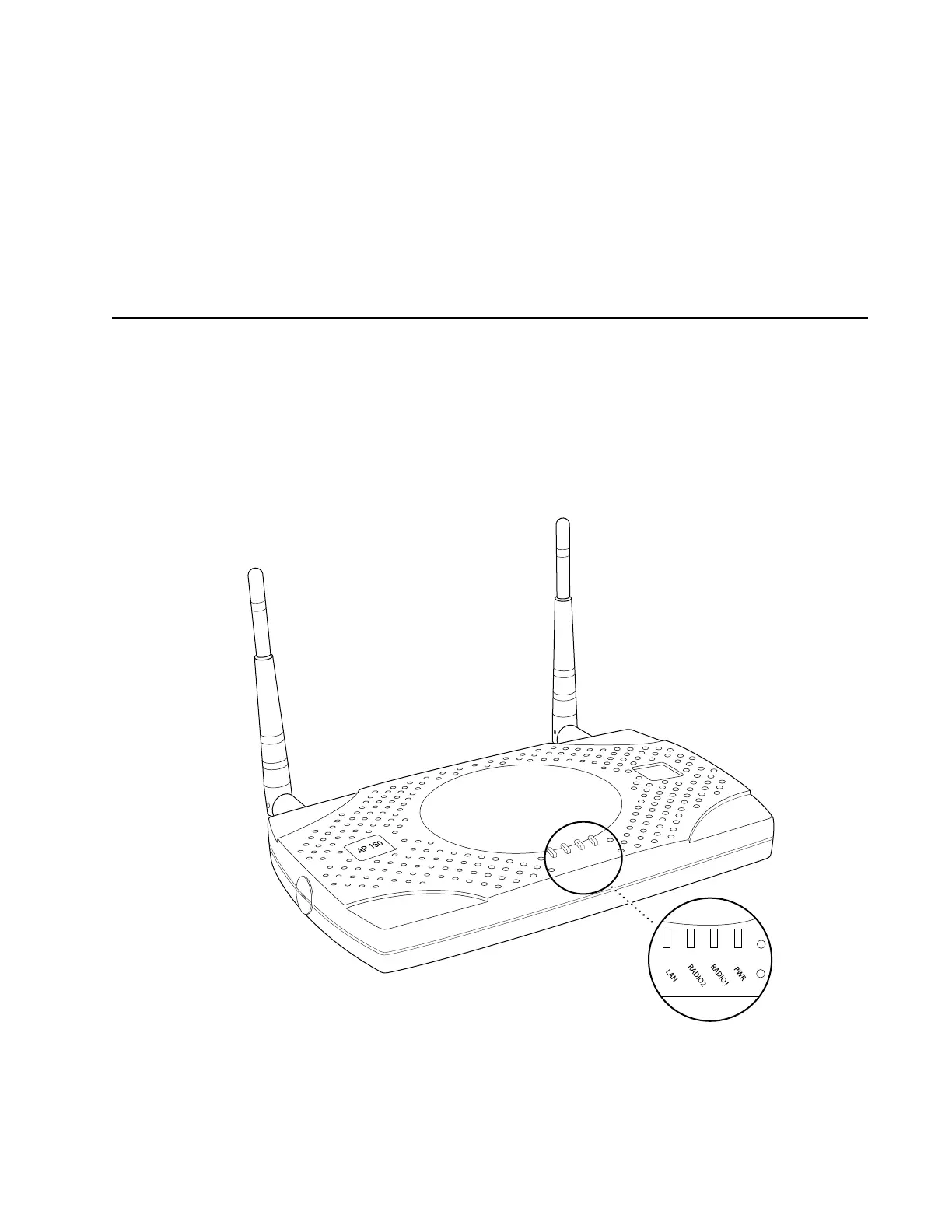
Checking LED Activity
Access point status LEDs are provided on the Ethernet connector and on the face of
the AP150.
AP150 Status LEDs
Four status LEDs on the face of the AP150 also light, as shown in Figure 33.
.
PWR
LAN
RADIO 2
RADIO 1
Status LEDs
00166
 Loading...