24 Meru Access Point Installation Guide
Installing the Access Point
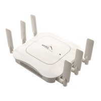
4. If using a separate power supply, connect the power cable to the power inlet connector shown in
Figure 14.
Figure 14: AP200 Connector Panel
Vertical Mounting
To vertically mount an AP:
1. Using the bracket holes as a template, mark the location on the wall for the two AP bracket
mounting screws. They are placed 4 ½ inches apart, center-to-center, one above the other. If you
are not using plastic wall anchors, you must center the mounting screws on a wall stud. If you do
not center the mounting screws on a wall stud, you must use plastic wall anchors.
CONSOLE
ANT 1
ANT 2
3.3 VDC
ETHERNET
0108
100/1000
Ethernet
Console
port
Antenna 1 Antenna 2
Power
inlet
Reset
(push to restore
default settings)
 Loading...