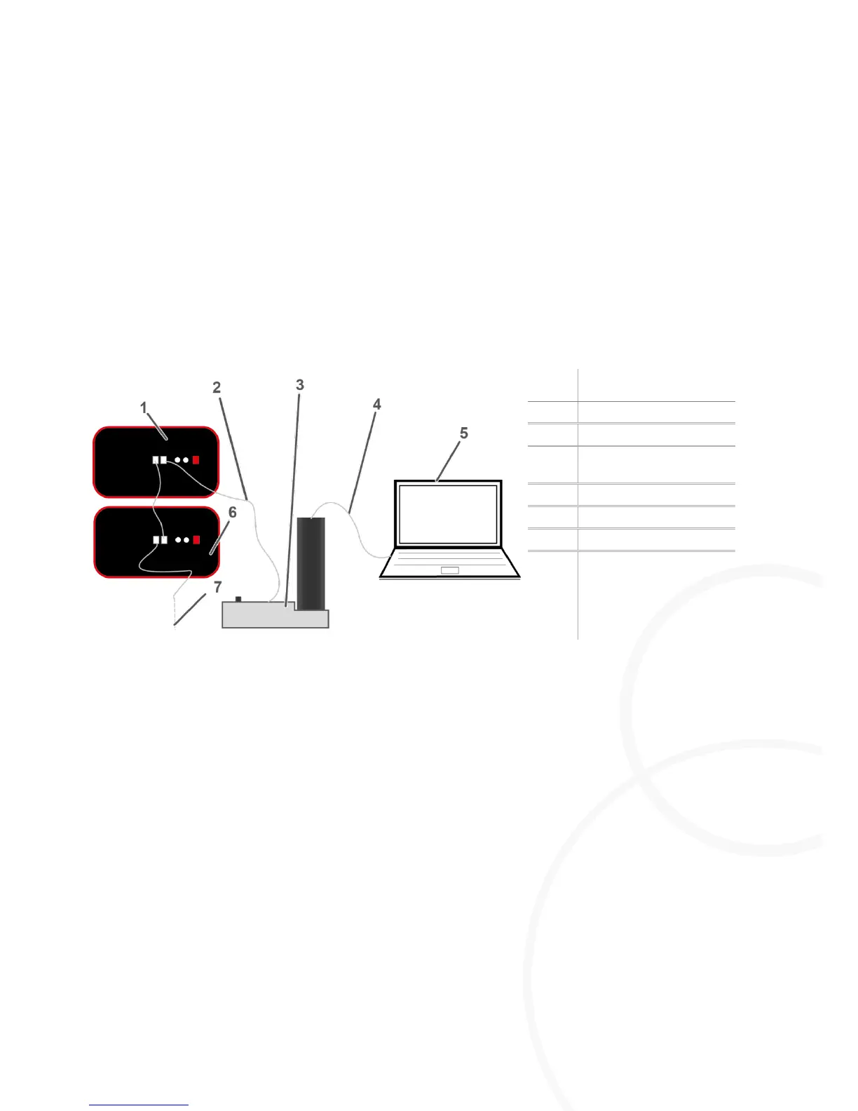
Connect the PC to the CAN-bus interface via USB cable.
Connect the CAN-bus interface with the first M=Light LED.
Connect the first M=light LED with the next M=Light LED via CAN-bus.
Assign a unique CAN-BUS address to all M=Light LEDs in the same CAN-bus line.
You can now parameterize and control the connected M=Light LEDs with the help of the
M=Light control software (section 5.3, page 22).
8.2. Switch-on of M=LIGHT LED via Flash-Bus
Remote controlled switch-on and switch-off of the M=Light LEDs is always performed by means of
the Flash H and Flash L signals at the Pin 1 and Pin 2 input. Pin 3 & 5 and Pin 4 & 6, respectively,
are bridged for voltage supply of the input assembly. Pin 7 and 8 remain unassigned.