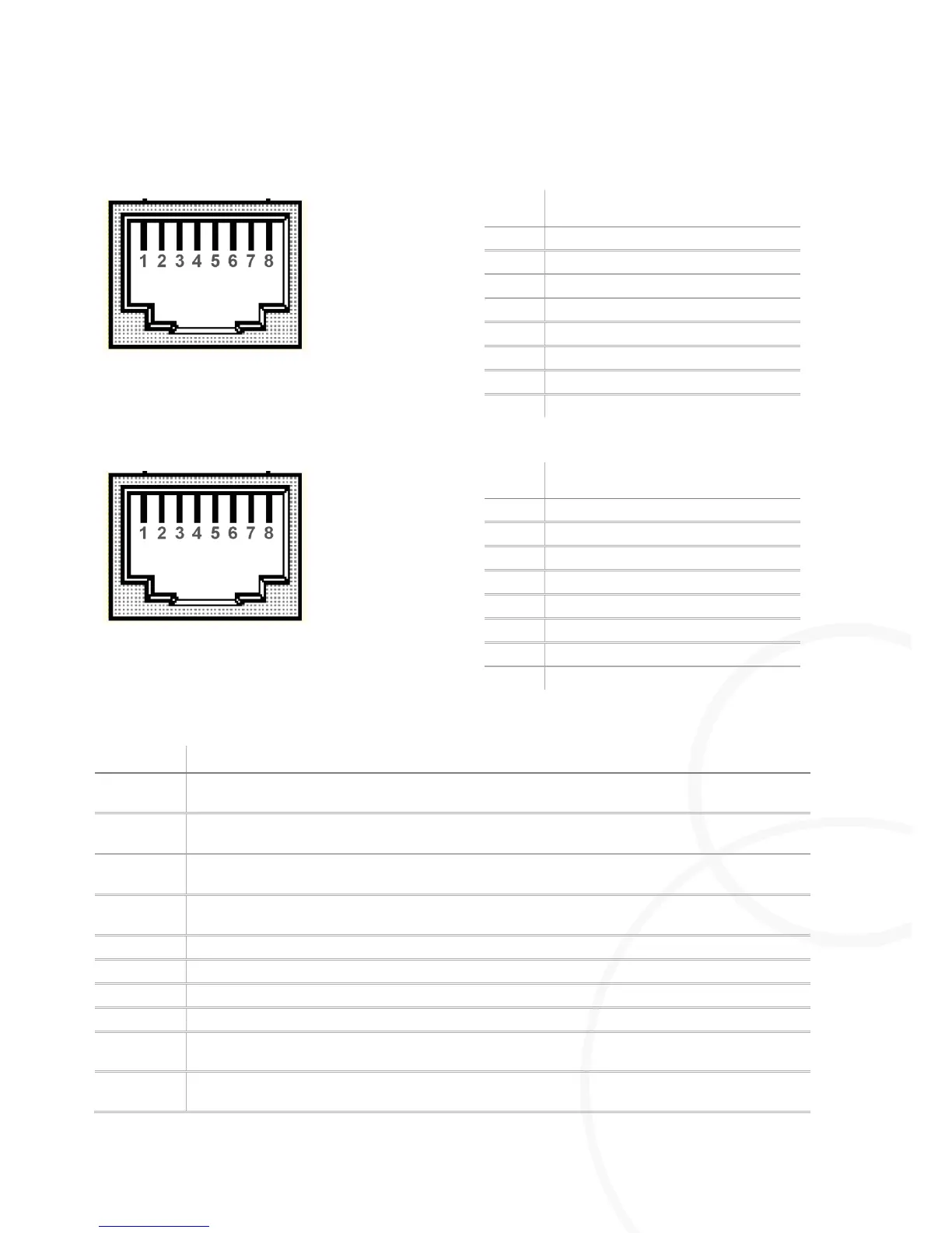
4.2.3. Contact Assignment of CAN-Bus Connections
Figure 8: Contact assignment of CAN-bus IN
Figure 9: Contact assignment of CAN-bus OUT
Input for physical CAN-bus signal for switching the M=Light LED on and off. Also used as output in
Master mode.
Input for physical CAN-bus signal for switching the M=Light LED on and off. Also used as output in
Master mode.
Ground connection to previous M=Light LED (Term-) for switch-off of the terminating resistor at the
Flash and CAN output.
9V output connection to previous M=Light LED (Term+) for switch-off of the terminating resistor at
the Flash and CAN output.
Ground connection for 9V output
Input for physical CAN-bus signal for parameterization of the M=Light LED.
Input for physical CAN-bus signal for parameterization of the M=Light LED.
Input connection from next M=Light LED for switch-off of the terminating resistor at the Flash and
CAN output.
Input connection from next M=Light LED for switch-off of the terminating resistor at the Flash and
CAN output.