Take into account the power rating (section 7.2, page 50).
Take into account the limit values for frequencies (section 7.2, page 50).
Do NOT supply components via multiple socket outlets.
The M=Light LED is now supplied with operating voltage.
Disconnecting Voltage Supply
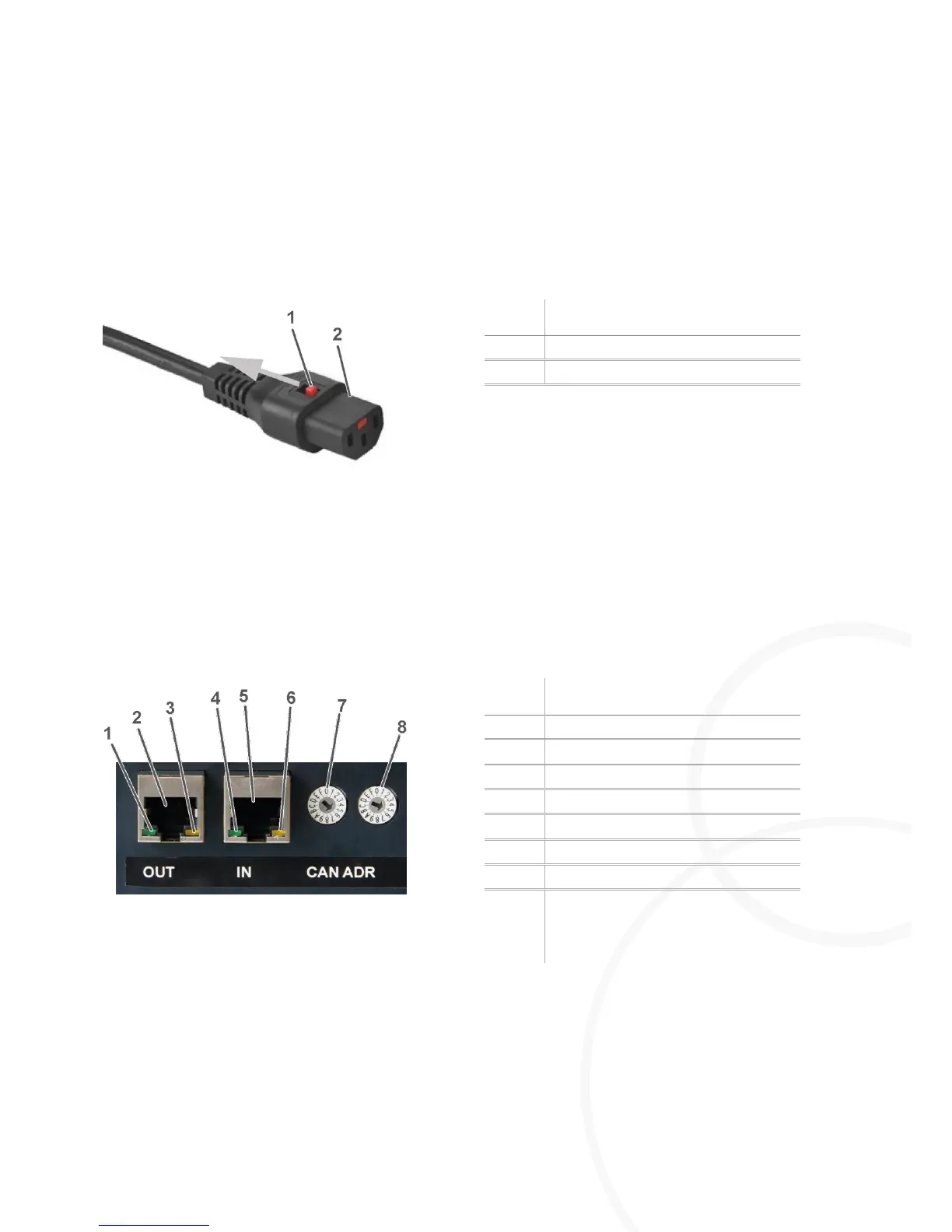
Figure 6: AC power cord set with IEC-lock
Pull back the lock at the female connector.
Pull out the male connector.
The M=Light LED is now disconnected from voltage supply.
4.2.2. Establishing Signal Connections
CAN-bus OUT (Figure 9, page 18)
CAN-bus IN (Figure 8, page 18)
Figure 7: CAN-bus on the rear side of the housing
Connect the CAN-bus interface with the control PC.
Connect the RJ45 input IN of the first M=Light-LED with the CAN-bus interface.
Connect the RJ45 output OUT of the first M=Light-LED with the input IN of the second M=Light-
LED.