8
2. Current Loop Connection
a. Making Connections
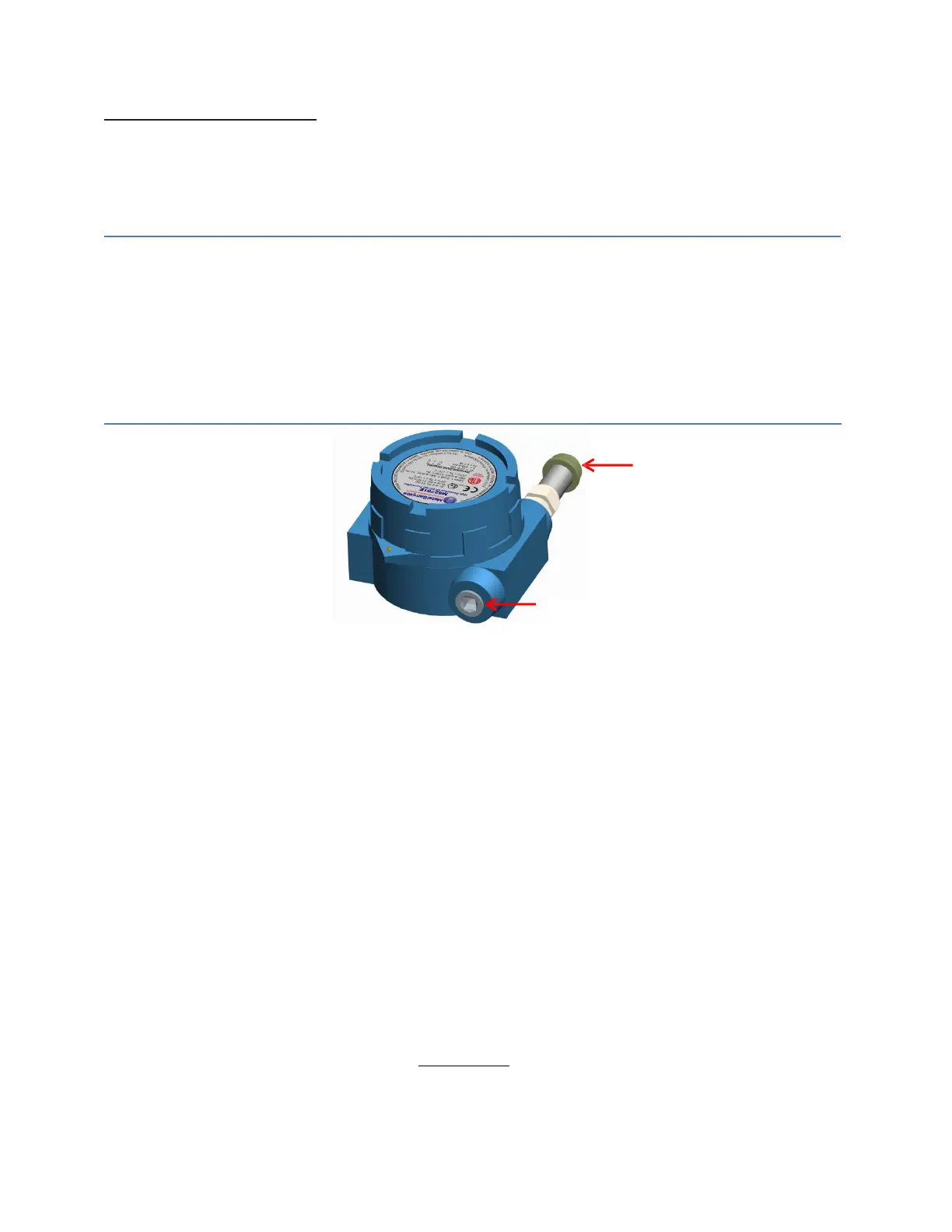
The MS2601E current loop connection wiring enters the transmitter through the 1/2" female NPT
conduit port shown in Figure 4 below. Please refer control drawing for wiring and Terminal
identification.
CAUTION:
When used in a hazardous area, the conduit or cable connections must be made in such
a way that all hazardous area requirements are met. Cable Glands and blanking plugs must be
certified for protection types ‘Ex db’ or ’tb’ and it should be rated for IP66.
ATTENTION: Lorsqu'ils sont utilisés dans une zone dangereuse, les connexions des conduits ou
des câbles doivent être réalisées de manière à ce que toutes les exigences relatives aux zones
dangereuses soient satisfaites. Les presse-étoupes et les obturateurs doivent être certifiés pour
les types de protection «Ex db» ou «tb» et doivent être classés IP66.
Probe Connector
Stem or Probe Cable
1/2” FNPT Conduit Port for
Field Wiring Entry
Figure 4. MS2601E current Loop Connector
The maximum permissible length of the current loop wiring between the MS2601E Transmitter and
the control system is determined by the control system supply voltage, the electrical resistance of the
current loop cable and the load of the control system input. If the Transmitter is to be installed in a
safe area, refer to section c. Wiring for a Safe Area Installation for details. If the Transmitter is to be
installed in a hazardous area, refer to section d. Wiring for a Hazardous Area Installation.
b. Grounding
The MS2601E enclosure is grounded internally through the wiring harness, but an additional, external
grounding terminal is provided as well. The enclosure should be grounded properly using the external
grounding terminal to ensure safe operation.
c. Wiring for a Safe Area Installation
For basic safe area wiring information refer to the circuit diagram shown on page 19. Use the following
equation to determine maximum permissible cable length:
=
(
10)
(
4 10
)(
)