5
ATMOS 41
2.2.2 CONNECT TO NONMETER LOGGER
The ATMOS41 can be purchased for use with non-METER (third party) data loggers. Refer
to the third-party logger manual for details on logger communications, power supply,
and ground ports. The ATMOS41 Integrator Guide also provides detailed instructions on
connecting sensors to non-METER loggers.
ATMOS 41 sensors can be ordered with stripped and tinned (pigtail) wires for use with screw
terminals. Refer to the third-party logger manual for details on wiring.
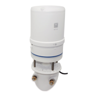
Connect the ATMOS41 wires to the data logger as illustrated in Figure2 and Figure3, with
the power supply wire (brown) connected to the excitation, the digital out wire (orange) to a
digital input, and the bare ground wire to ground.
Ground (bare)
Digital
communication (orange)
Power (brown)
Figure2 Pigtail wiring
NOTE: Some early ATMOS41 units may have the older Decagon wiring scheme where the power supply is white, the
digital out is red, and the bare wire is ground.
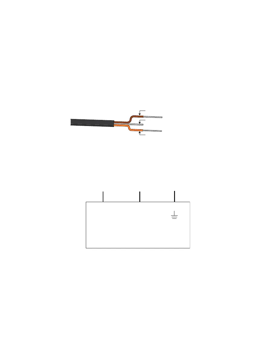
Excitation Digital
in
Data Logger
Ground
communication
(orange)
Ground
(bare)
Power
(brown)
Figure3 Wiring diagram
NOTE: The acceptable range of excitation voltages is from 3.6 to 15.0 VDC. To read the ATMOS41 with Campbell
Scientific data loggers, power the sensors off a 12-V port.
If the ATMOS41 cable has a standard stereo plug connector and needs to be connected
to a non-METER data logger, use one of the following two options.
Option 1
1. Clip off the stereo plug connector on the sensor cable.
2. Strip and tin the wires.
3. Wire it directly into the data logger.