13
TEROS 54
Excitation Digital in
SDI-12
3-wire
SDI-12
Data Logger
Ground
communication
(orange)
Ground
(bare)
Power
(brown)
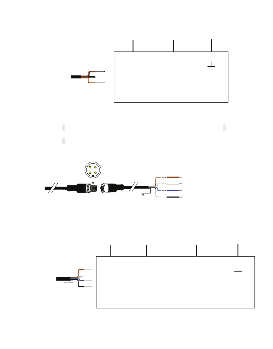
Figure7 Three-wire SDI-12 pigtail wiring digram
For RS-485, the power supply wire (brown) will be connected to the excitation, the digital
communication + wire (white) to a digital input (high), the digital communication – wire
(black) to a digital input (low) and the blue ground wire to ground. For SDI-12, both the digital
communication – and ground wires will both be connected to ground.
PIN 4 RS-485-B (black)
Shield
PIN 3 Ground (blue)
PIN 2 RS-485-A/SDI-12 (white)
PIN 1 Power + (brown)
3
4
1
2
sensor cable
From
probe or
sensor
Figure8 Four-wire M12 connector and pigtail adapter for use with screw terminals
Excitation Digital in
RS-485-A (+)
RS-485
Data Logger
Ground
Digital
communication
(white)
Ground
(blue)
Power
(brown)
Digital in
RS-485-B (–)
Digital
communication
(black)
Figure9 Four-wire M12 connector RS-485 wiring diagram