14
OPERATION
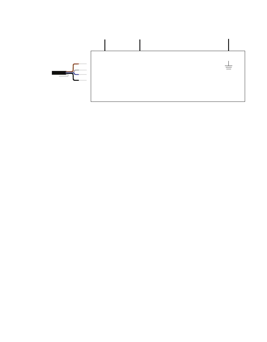
Excitation Digital in
SDI-12
4-wire M12
SDI-12
Data Logger
Ground
communication
(white)
Ground
(blue, black)
Power
(brown)
Figure10 Four-wire M12 connector SDI-12 wiring diagram
If the TEROS 54 cable has a standard stereo plug connector and needs to be connected to a
non-METER data logger, use one of the following two options.
Option 1
1. Clip off the stereo plug connector on the probe cable.
2. Strip and tin the wires.
3. Wire it directly into the data logger.
This option has the advantage of creating a direct connection and minimizes the chance of
the probe becoming unplugged. However, it then cannot be easily used in the future with a
METER readout unit or data logger.
Option 2
Obtain an adapter cable from METER.
The adapter cable has a connector for the stereo plug connector on one end and three
wires (or pigtail adapter) for connection to a data logger on the other end. The stripped and
tinned adapter cable wires have the same termination as seen in Figure6: the brown wire is
excitation, the orange is output, and the bare wire is ground.
NOTE: Secure the stereo plug connector to the pigtail adapter connections using adhesive-lined heat shrink to ensure
the probe does not become disconnected during use.
2.3 COMMUNICATION
The TEROS 54 communicates using different methods:
• DDI Serial
• SDI-12 communications protocol
• Modbus RTU communications protocol
• tensioLINK serial