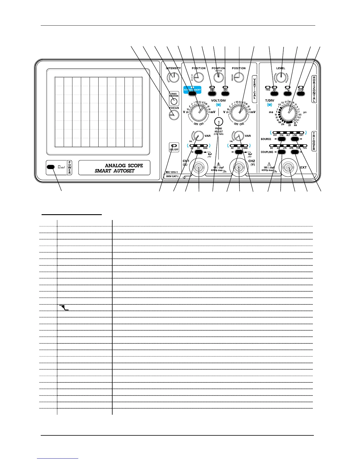
Description of marks:
1 - FOCUS
Trace focusing adjustment potentiometer
2 - TRACE ROTATION
Access hole to the trace rotation adjustment potentiometer
3 - INTENSITY
Trace intensity adjustment potentiometer
4 - AUTOSET/ABORT
Intermittent start key for the AUTOSET function or ABORT the result of the AUTOSET
5 - VOLT/DIV CH1
Selection switch for vertical sensitivity or switching channel CH1 off (CH1 OFF pos.)
6 - POSITION
Vertical framing potentiometer for the CH1 trace
7 - ADD
Key for activation of the channel addition mode
8 - POSITION
Horizontal framing potentiometer for the CH1 and CH2 traces
9 - -CH2
Channel CH2 inversion selection key
10 - POSITION
Vertical framing potentiometer for the CH2 trace
11 - VOLT/DIV CH2
Selection switch for vertical sensitivity or switching channel CH2 off (CH2 OFF pos.)
12 - x10
Horizontal expansion by 10 selection key
13 - LEVEL
Trigger level adjustment potentiometer
14 -
Trigger slope selection key
15 - T/DIV XY
Horizontal sweep speed selection key for traces and selection of XY mode
16 - AUTO
Triggered or automatic scanning mode selection key
17 - SOURCE
Trigger source scanning/selection left/right key
18 - COUPLING
Trigger filter scanning/selection left/right key
19 - EXT
External trigger input BNC plug
20 - COUPLING
Trigger filter scanning/selection left/right key
21 - SOURCE
Trigger source scanning/selection left/right key
22 - VAR CH2
Gain adjustment potentiometer for vertical channel CH2
23 - CH2 (Y)
BNC input plug for channel CH2 (or for the Y channel in XY mode)
24 - COUPLING CH2
Input coupling scanning key or selection of the channel CH2 ref.
25 - PROBE ADJUST
Access hole to the calibration signal
26 - CH1 (X)
BNC input plug for channel CH1 (or for the X channel in XY mode)
27 - COUPLING CH1
Input coupling scanning or selection of the channel CH1 ref. key
28 - VAR CH1
Gain adjustment potentiometer for vertical channel CH1
29 - ON/OFF
On/Off indicator
30 - POWER
On/Off switch
 Loading...