Chapter II
22
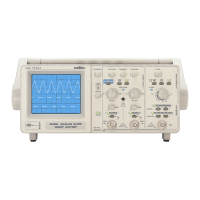
30 MHz
oscilloscope
6.3. Trigger system
Specifications Comments
Sources
Sensitivity in normal mode - Trigger from 0 to 40 MHz
CH1 or CH2 0.5 div. 0 to 10 MHz
1 div. 10 to 20 MHz
1.5 div. 20 to 40 MHz
ALT Source depending on display mode:
CH1 trigger CH1
CH2 trigger CH2
ALT trigger CH1 then CH2
CHOP ditto ALT mode
ADD trigger CH1
-CH2 trigger CH2
LINE synchronization on mains
EXT 50 mVrms 0 to 10 MHz protection ± 420 V (DC + AC peak,
f < 1 kHz)
100 mVrms 10 to 20 MHz
input impedance: 1 MΩ // 25 pF
700 mVrms 20 to 40 MHz
Filters (coupling)
Bandwidth
AC 10 Hz to 40 MHz
DC 0 Hz to 40 MHz
LFR (rejection) 10 kHz to 40 MHz
HFR (rejection) 0 Hz to 10 kHz
Horizontal mode
AUTO Automatic mode
Normal Triggered mode
Slope
Falling edge
Rising edge
Level
Adjustment range:
Normal mode: ±12 divisions
6.4. Calibration signal
Shape rectangular
Amplitude 2.5 V ± 1%
Frequency 1 kHz ± 1%
6.5. AUTOSET mode
• Signal search time ≈ 5 s
• 25 Hz ≤ signal frequency ≤ 30 MHz
• 50 mVpp ≤ amplitude without probe ≤ 160 Vpp
6.6. General characteristics
Cathode ray tube
Type rectangular 13 cm diagonal with internal grid
Graticule 8 vertical divisions with 5 sub-divisions
10 horizontal divisions with 5 sub-divisions
1 division = 1 cm
Screen GY phosphorus with average persistence
Trace adjustment of trace rotation, focusing, light intensity
Total acceleration voltage 2 kV
 Loading...