■■■■■■■■■■■■■■■■■■■■■■
2 Construction of the 807 Dosing Unit
807 Dosing Unit
■■■■■■■■
5
2 Construction of the 807 Dosing Unit
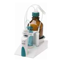
2.1 Total view
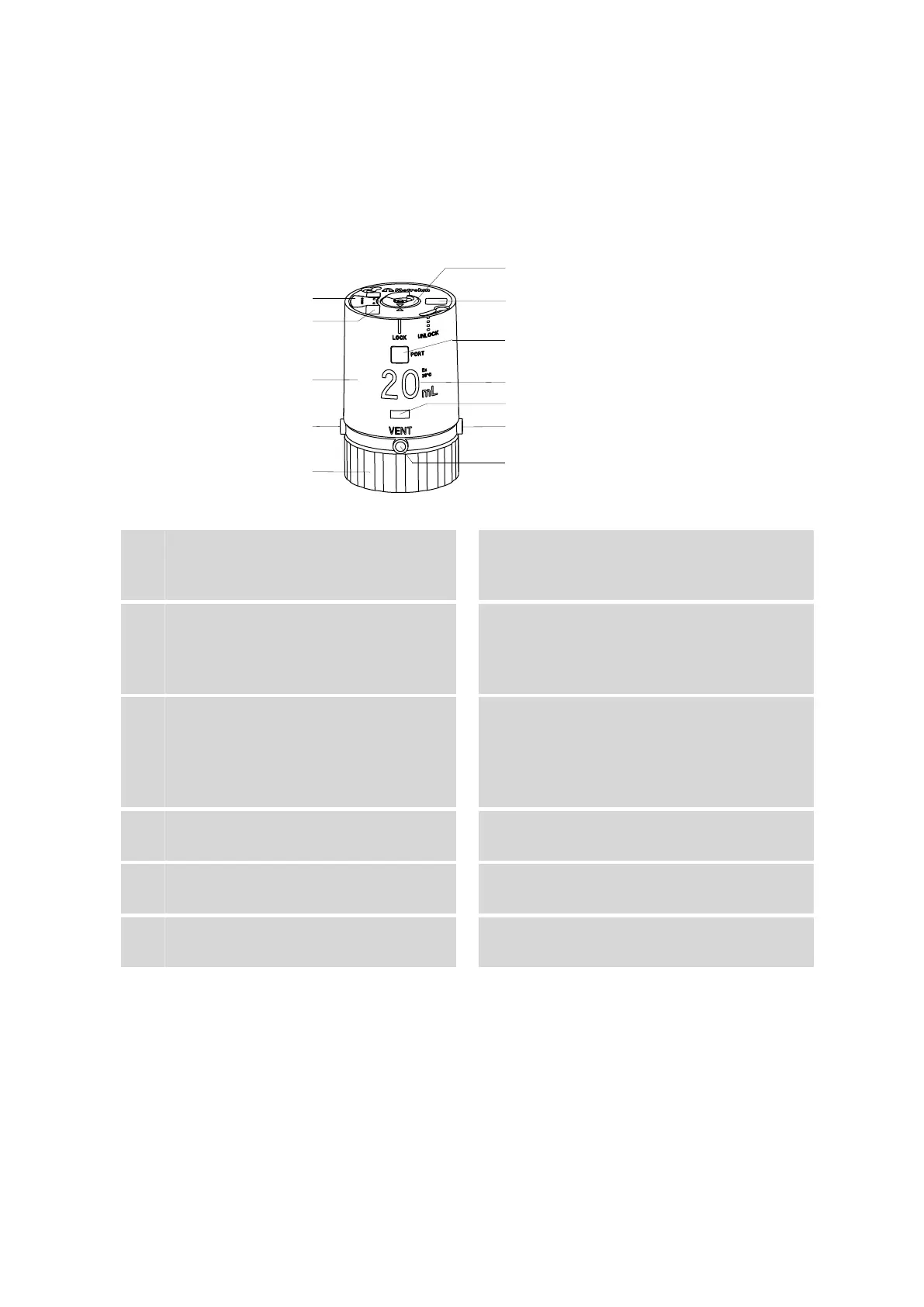
Figure 1 807 Dosing Unit
1
Data chip
Contains all specifications for the dosing
unit.
2
Coding magnet
For automatic recognition of the volume of
the dosing unit.
3
Housing
With data chip, coding magnets, locking
button and specifications concerning the
dosing unit.
4
Port 1
Dosing port 1. Dosing output for solution.
5
Fixing ring
For fastening the dosing unit onto a reagent
bottle.
6
Centering tube
Is actuated by Dosino and rotates the entire
inner cylinder unit, together with dosing cyl-
inder, cylinder base and the integrated valve
disc.
7
Serial number, order number and bar-
code
8
Port display
Displays the port currently opened.
9
Nominal volume
Volume of the dosing cylinder.
10
Locking button
For locking and unlocking the housing.
11
Port 3
Dosing port 2. Dosing output for solution.
12
VENT port
For deaerating the reagent bottle.