4 2 BAC 70 en
3.1 Replacement of the sealing element
Please proceed as follows when you want to replace
the Sealing element on the heavy-duty valve:
1. Remove the heavy-duty valve when it is in the 0° position
(completely closed). Instructions on how to remove the
valve can be found in section 1 of the instruction manual
2B70.
2. Secure the heavy-duty valve in position, so that it
cannot move or tip over.
3. Swivel the Shut-off disc 180°, so that the sealing ele-
ment is exposed. Secure the shut-off disc - for
example with wooden wedges - in order to eliminate
the danger of scraching the parts. Make sure that
you do not damage the sealing area of the disc
while you are doing this.
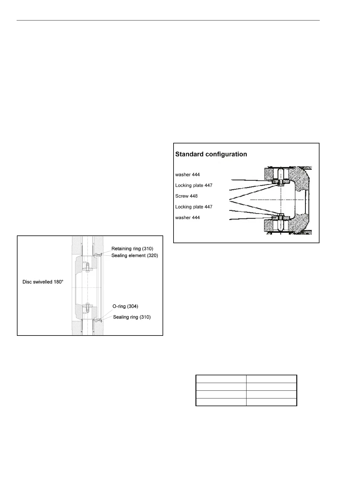
4. Remove the retaining ring (see the sectional draw-
ing). The sealing ring is now exposed and can be
removed. If it is stuck, you can screw screws into the
two threads of the sealing ring and remove it with
their help.
5. Replace the sealing element (320), the O-ring (304)
and the sealing ring (301) now. Fit the retaining ring
(310) again as a final operation (see the illustration
on page 6).
6. Check that the heavy-duty valve is tight before
installing it again. Information about the installation
operations can be found in section 1 of the instruc-
tion manual 2B70.
Fig. 3 Replacement of the o-ring
3.2 Replacement of mechanical parts
Proceed as follows to replace mechanical parts:
1. Remove the adapter first of all.
2. Swivel the shut-off disc 180° C, so that the sealing
element is exposed. Secure the shut-off disc - for
example with wooden wedges - in order to eliminate
the danger of crushing. Make sure that you do not
damage the sealing area of the Shut-off disc while
you are doing this.
3. On standard versions of Type A that are designed for
particularly high pressure levels, you need to undo
two Screws (448) and remove the washer (444) as
well as the safety plate (447) (see the figure below).
4. Undo the screws (433) and remove the cover (430
and 437) (see the figure on page 9).
5. Undo the screws (432) on the two bearing bushings
(410).
6. Put two screws in the threads and pull the bearing
bushing and the shaft out.
You can now replace the following parts:
• the shaft (402),
• the actuator shaft (401),
• the bearing bushings (410, 424),
• the O-rings (470, 419),
• the backup rings (476),
• the U-ring (475),
• the thrust bearing (404, 405) and
• the disc (202).
7. Installation is carried out by completing the same
operations in the opposite order. Attend the torque
for the screws (448). They shall be mounted with a
special grease and the torque meter.
8. Check that the valve is tight before fitting it again.
Information about the installation operations can be
found in section 1 of the instruction manual 2B70.
Size MT [Nm]
M8 20
M10 45
M12 70
 Loading...