1 X 70 en 3
1 GENERAL
1.1 Scope of the manual
This manual provides the essential information on the
use of XT/XA-series ball valves. For further information
on actuators and other instruments, which are covered
only briefly, please refer to separate manuals on their
installation, use and maintenance.
1.2 Valve description
XT/XA-series valves are flanged ball valves and are
either metal or soft seated. Valves have two-piece bod-
ies with bolted body joints. The ball and the shaft are
separate parts and a shaft blow-out is prevented by a
separate thrust ring/pin and retaining plates.
A spline driver transmitting the shaft torque to the ball
connects the shaft with the ball. In 1" and 1 1/2" valves
the shaft directly drives the slot in the ball (no separate
driver).
The valve is tight in both flow directions. Tightness is
based on pipe pressure, i.e. the pressure differential
over the valve forces the ball against the downstream
seat. The arrow in Figures 1 and 2 shows the recom-
mended flow direction with H seat construction.
The construction of the valves may vary in accordance
with customers’ wishes. The construction details are
indicated in the type code in the identification plate. For
more information about the type code, see section 12.
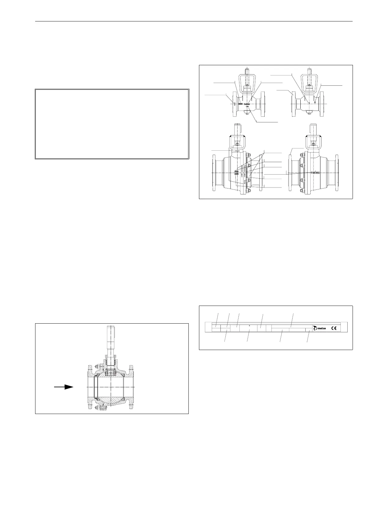
1.3 Valve markings
Body markings are cast or stamped on the body (see Fig-
ure 2). The identification plate (Figure 3) is on the valve
flange.
Identification plates have the following markings:
1. Body material
2. Shaft material
3. Trim material
4. Seat material
5. Maximum and minimum operating temperatures
6. Maximum shut-off pressure differential/temperature
7. Pressure class
8. Type code
9. Number of the list of valve manufacturing parts
10. Model
NOTE:
As the use of the valve is application-specific, a
number of factors should be taken into account when
selecting the application. Therefore, some of the situa-
tions in which the valves are used are outside the
scope of this manual.
If you have any questions concerning the use or appli-
cation of the valve, contact Metso’s Automation busi-
ness for more information.
Fig. 1 Construction of an XT/XA-series valve,
sizes 1"-8"
Recommended
flow direction for
valves with H seat
Fig. 2 Valve markings
Fig. 3 Identification plate
Batch number
Nominal size
Id plate
Body material
Batch number
Id plate
Foundry’s
Nominal size
Pressure class
Body material
Manufacturer’s
Casting no.
Foundry’s mark
mark
Manufacturer’s
mark
mark
Casting no.
BODY
TRIM
SHAFT
SEAT
T max
T min
MAX. OPER. ps
at
RATING TYPE
No.
MOD
ATTENTION : READ INSTRUCTIONS BEFORE INSTALLATION OR SERVICING. CONTACT METSO AUTOMATION FOR COPY.
MADE BY METSO AUTOMATION
XXXX
(1) (2) (5) (7) (8)
(3)
(4)
(6) (9)
(10)

 Loading...