CHAPTER 3: AMPLIFICATION AND AUDIO
16
To calculate the load impedance for the looped loudspeak-
ers, divide 10 kOhms (the input impedance for a single
UPQ-1P) by the number of looped loudspeakers. For exam-
ple, the load impedance for 10 UPQ-1P loudspeakers is
1000 ohms (10 kOhms / 10). To drive this number of looped
loudspeakers, the source device should have an output
impedance of 100 ohms or less. This same rule applies
when looping UPQ-1P loudspeakers with other self-pow-
ered Meyer Sound loudspeakers and subwoofers.
NOTE: Most source devices are capable of
driving loads no smaller than 10 times their
output impedance.
NOTE: Make sure that all cabling for looped
loudspeakers is wired correctly (Pin 1 to Pin 1,
Pin 2 to Pin 2, and so forth) to prevent the polarity
from being reversed. If one or more loudspeakers in a
system have reversed polarity, frequency response
and coverage can be significantly degraded.
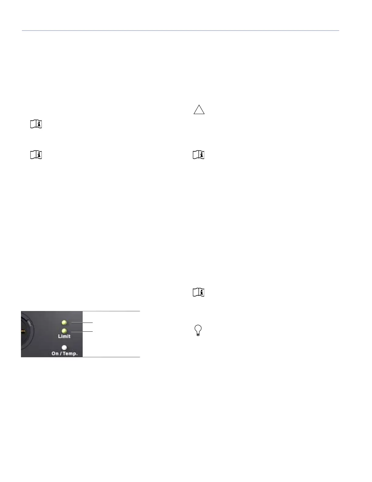
Limit LEDs
The low- and high-frequency drivers for the UPQ-1P loud-
speaker is powered by separate amplifier channels, each
with their own limiter. Limiting activity is indicated with the
two yellow Limit LEDs. The top LED indicates limiting for the
high-frequency channel and the bottom LED indicates limit-
ing for the low-frequency channel. When engaged, a chan-
nel’s limiter not only protects the driver, but also prevents
signal peaks from causing excessive distortion in the ampli-
fier’s channel, thereby preserving headroom and maintaining
smooth frequency responses at high levels. When a chan-
nel’s level returns to normal, below the limiter’s threshold,
limiting ceases.
The UPQ-1P loudspeaker performs within its acoustical
specifications at normal temperatures when the Limit LEDs
are unlit, or if the LEDs are lit for two seconds or less and
then turn off for at least one second. If an LED remains lit for
longer than three seconds, that channel enters hard limiting
where:
Increases to the input level have no effect.
Distortion increases due to clipping and nonlinear driver
operation.
The driver is subjected to excessive heat and excursion,
which will compromise its life span and may eventually
lead to damage over time.
CAUTION: The Limit LEDs indicate when a
safe, optimum level is exceeded. If a UPQ-1P
loudspeaker begins to limit before reaching the
required SPL, consider adding more loudspeakers to
the system.
NOTE: The UPQ-1P loudspeaker uses optical
limiters that add no noise and have no effect
on the signal when the limiters are not engaged and
the Limit LEDs are not lit.
On/Temp LED
When the UPQ-1P loudspeaker is powered on, its On/Temp
LED turns green. In the event that the temperature of the
heatsink reaches 85°C (185°F), the On/Temp. LED on the
rear panel turns from green (On) to red (Temp.) and the lim-
iter threshold is lowered to a safe level to prevent the system
from overheating. Under high temperature conditions the
output level is reduced by approximately 6 dB.
When the heatsink temperature decreases to 80°C (176°F),
the On/Temp. LED changes from red to green and the limiter
threshold returns to normal.
NOTE: When the On/Temp LED is red, this is
an indication that the unit is reaching its maxi-
mum dissipation and a reduction in SPL is recom-
mended.
TIP: When the UPQ-1P loudspeaker is con-
nected to an RMS network, the RMS software
provides additional feedback on the loudspeakers’
operating temperature. For more information, see
Chapter 6, “The RMS Remote Monitoring System.”
Amplifier Cooling System
The amplifier for the UPQ-1P loudspeaker relies on natural
convection for cooling at low to mid audio levels; it is fan-
assisted at high audio levels.
Limit LEDs
High-frequency limiter LED
Low-frequency limiter LED
 Loading...