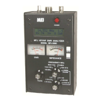
MFJ-266B HF/VHF/UHF Antenna Analyzer Instruction Manual
2012 MFJ Enterprises, Inc. Version 1D 7
C: 4.6 to 9.6 MHz (60,40 Meters)
D: 8.5 to 18.7 MHz (30,20,17 Meters)
E: 17.3 to 39 MHz (17,15,12,10 Meters)
F: 38.7 to 71 MHz (6 Meters)
Before moving on to the next section, take time to review the MFJ-
266B’s basic set-up procedures. Operation becomes second nature
quickly, but should you need it, there’s a supplemental "quick guide" in
the back for reference (Section 8.0). The remainder of the manual will
focus on general instructions and helpful tips for making accurate
measurements.
5.0 ACCURACY LIMITS
The MFJ-266B will serve as your “eyes and ears” when working with RF
systems, and it can deliver results that rival units costing thousands of
dollars. However, all handheld analyzers share certain limitations, and
being aware of them will help you to achieve more meaningful results.
5.1 SWR Measurements and Local Interference
The MFJ-266B (and other hand-helds) use a broadband diode detector
that is open to receiving signals across the entire radio spectrum. Most of
the time, the unit's built-in stimulus generator is powerful enough to
overcome any lack of front-end selectivity and override stray pickup.
However, a powerful transmitter located nearby could inject enough RF
energy into the detector to disrupt readings. If this condition occurs,
performance will become erratic and SWR readings may appear higher
than they really are.
5.2 Checking for Local Interference
Unlike many analyzers, the MFJ-266B has an onboard function for
identifying local interference. Simply switch to the analyzer's Frequency
Counter (FC) mode and note the readings you obtain with the antenna
connected. If a strong signal (>100 mV) registers on the field-strength
display (FS) and the counter shows the frequency of a known local
broadcast station or radio service (f:), then suspect interference. If the
interfering source can't be turned off or your antenna can't be moved to a
different location, you may need to use a station transceiver and a thru-
line directional Wattmeter to complete the adjustments.
5.3 Detector Linearity and Accuracy
Diode detectors typically become non-linear at very low voltages.
Because of diode non-linearity, it's not uncommon for two identical
analyzers to show slightly different readings when checking a load with


 To Next Page