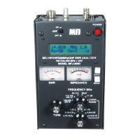
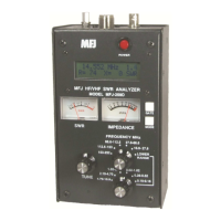
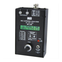
MFJ-266B HF/VHF/UHF Antenna Analyzer Instruction Manual
2012 MFJ Enterprises, Inc. Version 1D 11
(3.) Divide the present frequency by the desired frequency (ex 14.050 ÷
14.200 = .989)
(4.) Multiply the present length by the result (33.3 feet x .989 = 32.94
feet)
Note that this formula applies to full-sized antennas, but not to elements
shortened by coils, traps, or capacitive hats.
6.6 Antenna matching
If your antenna doesn’t exhibit 1:1 SWR at the minimum SWR
frequency, then some mismatch is present relative to 50-Ohms. For
simple dipoles and ground-independent verticals, mounting height above
ground may be the primary cause. Generally, it’s best to ignore SWR
readings under 2:1 and mount these antennas as high as possible where
they’ll perform best. For antennas that feature adjustable matching
networks (Yagis etc), SWR can usually be improved by following the
manufacturer’s antenna setup instructions. Note that matching and tuning
settings may interact, so readjustment of both the antenna’s element
length and matching network may be needed to obtain best results.
6.7 Matching Antennas Through A Tuner (ATU)
If your antenna can’t be tuned or matched to an acceptable SWR level by
making physical adjustments, then an external antenna tuner (ATU)
should be installed. The MFJ-266B may be used in conjunction with the
tuner to make adjustments without the need to transmit test signals over
air. Simply connect the analyzer to the tuner input (radio side) through a
short patch cable. Select the Analyzer mode, set up the Band, and Tune
for the desired frequency of operation. Then, adjust the antenna-tuner's
controls following the manufacturer's recommendations until SWR
approaches 1:1. Remove the analyzer, reconnect the radio, and the load
will be pre-matched to the radio's 50-Ohm operating impedance.
6.8 Antenna Impedance Readings
The MFJ-266B displays complex impedance and impedance magnitude
readings on the same screen with the SWR reading. However, when
measuring through coax, remember that the impedance readings are
phase-shifted values appearing at your end of the cable and not the actual
feedpoint impedance of the antenna itself (Section-5.4). As a “work-
around” strategy, it’s possible to measure the antenna’s actual impedance
remotely if the feedline is cut to an exact electrical half wavelength. In a
half-wavelength line, the phase shift is a full 360 degrees, which
electrically rotates the analyzer’s calibration plane back into alignment
with the load. However, this strategy only works at one frequency and
errors compound quickly if your cable is multiple half-wavelengths long.
As a practical matter, unless you have an advanced working knowledge


 To Next Page