MFJ-266B HF/VHF/UHF Antenna Analyzer Instruction Manual
2012 MFJ Enterprises, Inc. Version 1D 4
3.2 Main Menu Screen
The main menu screen has two purposes:
(1.) Power Supply Voltage: Appears on the right side of the screen. If it
falls outside the 3.5 to 5V operating window of the battery packs, be sure
to change batteries or make power supply adjustments.
(2.) Operating Mode Prompt: On the left side of the screen. This
prompts you to select between the two primary operating modes (see
below).
D >FC DC:12.00V
U >ANT Analyzer
Supply Voltage"Down" for Counter
"Up" for Antenna Analyzer
(3.) (D >FC) Press the “Down” button to select Frequency Counter
mode.
(4.) (U > ANT Analyzer) Press the “Up” button to select the Antenna
Analyzer mode.
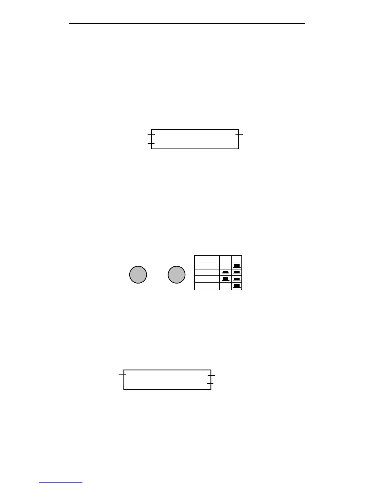
3.3 Frequency Counter Mode (D -> FC)
In this setup, the MFJ-266B functions as a 1-500 MHz frequency
counter. Note that the BAND SELECT switch B must be "up" in the HF
position for the counter mode to activate. If switch B is down, an error
message will prompt you to change the band setting to HF.
A
B
BAND SELECT
BAND A B
HF X
VHF
UHF
Counter X
UP
When a signal is applied to the Antenna jack, the frequency is displayed
in MHz. Two gate speeds are available. The default gate speed is Fast (or
Fg -- see the top right-hand side of the display). The fast gate provides 1-
kHz resolution. The alternative gate speed is Slow (or Sg), which
provides 100-Hz resolution. To change the gate speed:
(1.) For Fast Gate, press the UP button.
(2.) For Slow Gate: press the DOWN button.
Fg f: 010.000 MHz
REF FS: 100mV
Gate Speed
Frequency Readout
Relative Field Strength
The Counter mode also provides relative Field Strength (REF FS). This
feature is useful for conducting relative field-strength tests, estimating
input levels to the counter, and detecting local signals that could impact
SWR accuracy (see Section 7.2).