MFJ-266B HF/VHF/UHF Antenna Analyzer Instruction Manual
2012 MFJ Enterprises, Inc. Version 1D 15
(7.) Re-cut the cable to that length.
*Note that the impedance value may not drop to zero, but it will
begin to increase again as you continue to tune past the null. If
the null reading is broad, choose a frequency at the center.
7.7 Determining Velocity Factor
If you have coax cable with an unknown velocity factor, you can
determine it quickly using the following procedure:
(1.) Set the MFJ-266B up in Analyzer mode (Section-3)
(2.) Set the Range to HF and the Band to E (Section-4)
(3.) Make a 1/4-λ stub from 9 feet of the unknown cable and connect it to
the analyzer (open end)
(4.) Rotate Tune for minimum impedance magnitude reading. Write
down the frequency (MHz)
(5.) Divide 246 by this frequency to find the free-space 1/4-λ wavelength
in feet (L = 246
÷
f MHz)
(6.) Divide 9 (actual length) by free-space 1/4-λ wavelength to get the
Velocity Factor (VF =9
÷
L)
Note that there is nothing magical about the 9-foot stub length, other than
it falls conveniently within the limits of Band E’s tuning range. Other
lengths could be used. Shorter stubs will yield poorer accuracy and long
ones may needlessly waste useful cable.
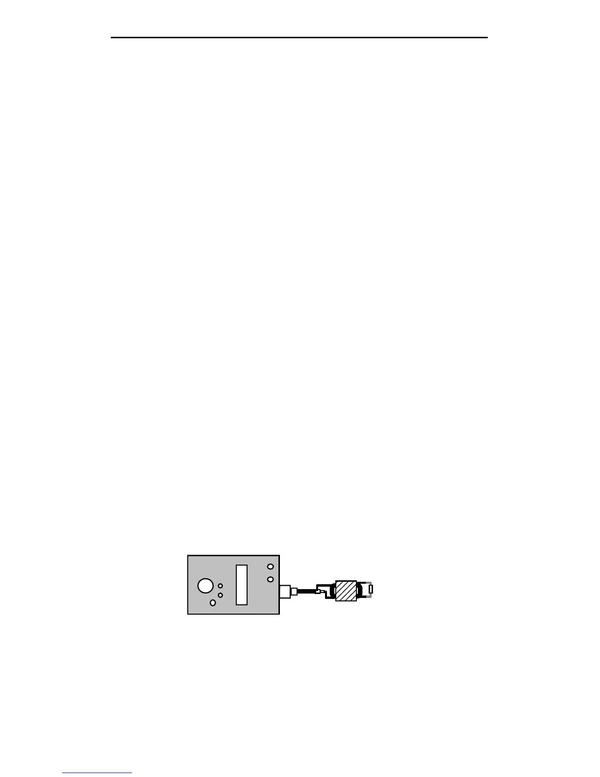
7.8 Testing RF Transformers
Broadband HF-matching transformers wound for the 12.5 to 200 Ohm
range may be tested using the MFJ-266B. Connect the 50-Ohm (primary)
side to the analyzer connector using a short pigtail and attach the
appropriate resistive load across the secondary side (always use a non-
inductive resistor). Next:
MJ-266
Load
Transformer
(1.) Set the MFJ-266B up in Analyzer mode (Section-3)
(2.) Set the Band Select to HF and the Band-Mode to the desired
frequency range (Section-4)
(3.) Rotate Tune across the frequency range and note SWR. Change
bands, as needed.
 Loading...


