MFJ-266B HF/VHF/UHF Antenna Analyzer Instruction Manual
2012 MFJ Enterprises, Inc. Version 1D 17
8.0 QUICK GUIDE TO ANALYZER CONTROLS AND
FUNCTIONS
Power: Use only 1.5-V Alkaline Batteries. External power must be 10.8-
12.5 Vdc, well regulated. Power plug: 2.1-mm, positive (+) to center
pin.
Power Up: Press PWR, wait for the Main Menu to come up.
Power Up + Backlight: Press PWR then UP, hold until screen lights and
Main Menu comes up.
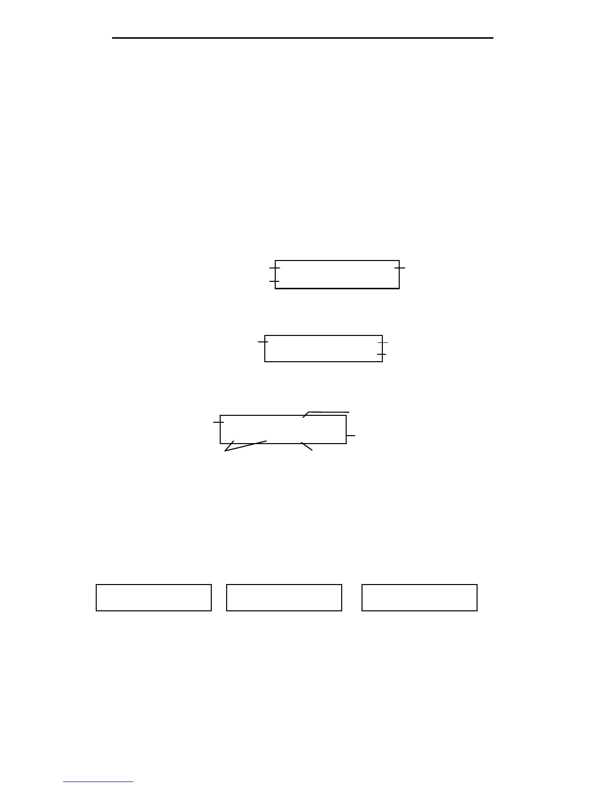
Main Menu Screen:
D >FC DC:12.00V
U >ANT Analyzer
Check Supply Voltage Press Down button for Counter Mode
Up button for Antenna Analyzer Mode
Counter Mode Screen:
Fg f: 010.000 MHz
REF FS: 100mV
Set Gate Speed: Up = Fast, Down = Slow
Incoming Signal Frequency Readout
Relative Field Strength
Analyzer Mode Screen:
50+j 0 50 1.0
Stimulus Frequency
Band (Frequency) Selection
SWR (1.0:1)
10.000MHz D SWR
Impedance MagnitudeComplex Impedance
L/C Mode:
Measure C: Press and hold Up, press Power On
Measure L: Press and hold Down, press Power On
5.000MHz D C=
122 pF
Capacitance
Frequency Band
5.000MHz D L=
10.200 uH
Inductance
Frequency Band
5.000MHz D C=
Xc>1.5k
Frequency Band
Reactance out of Range
Change Stimulus Frequency
 Loading...


