MFJ-869 MFJ Giant automatic SWR/Wattmeter Instruction Manual
© 2009-2010 MFJ Enterprises, Inc.
7
• RS-232: DB-9 female connector for connecting to the computer’s RS-232 serial port to update
firmware. Check http://www.mfjenterprises.com/support.php
for the latest version of the firmware.
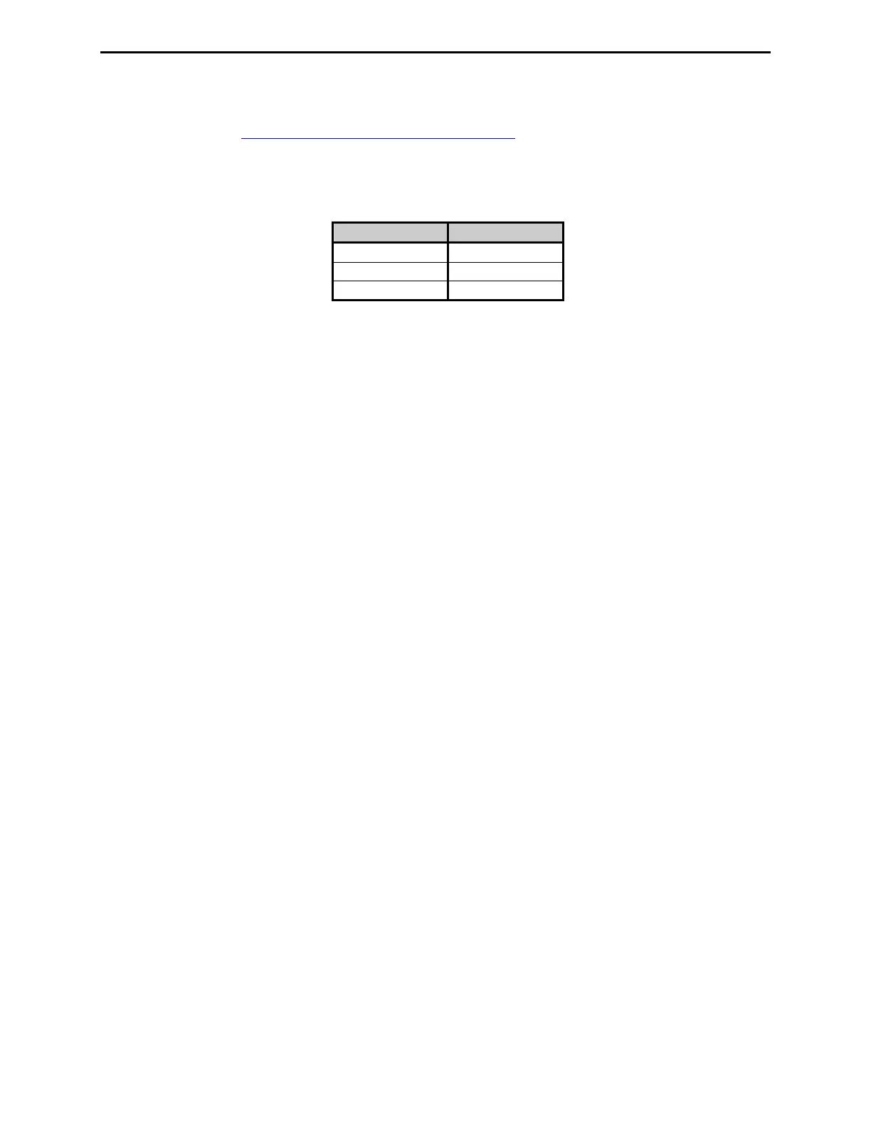
• RLY: 3.5 mm stereo phone jack connected to a high-speed reed relay switch with the tip normally
closed (NC), the ring normally open (NO), and the sleeve as common (COM). The relay switch
toggles position when the SWR is above the alarm SWR.
Connection Relay Switch
Tip NC
Ring NO
Sleeve COM
• Ground: Wing-nut terminal for RF ground wire connection.
• Antenna: SO-239 connector for coax cable from antenna or dummy load.
• Transmitter: SO-239 connector for coax cable from transmitter or transceiver.
Installation
1. Place the wattmeter in a convenient location at the operating position.
2. Install the wattmeter between the transmitter and the desired antenna. Use good quality coaxial cable
(such as RG-8/U) to connect the transmitter (or amplifier) to the rear panel connector marked
TRANSMITTER.
3. Connect the antenna to the rear panel connector marked ANTENNA.
4. A GROUND post is provided for an RF ground connection.
5. Connect a 12 to 15 VDC power source capable of 350 milliamps to the rear panel jack marked
POWER.