ENGLISH
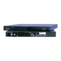
2.5 Communication Ports
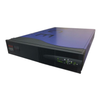
Connection of RS232 or USB communication port (optional)
The RS232 and USB communication ports cannot operate simultaneously.
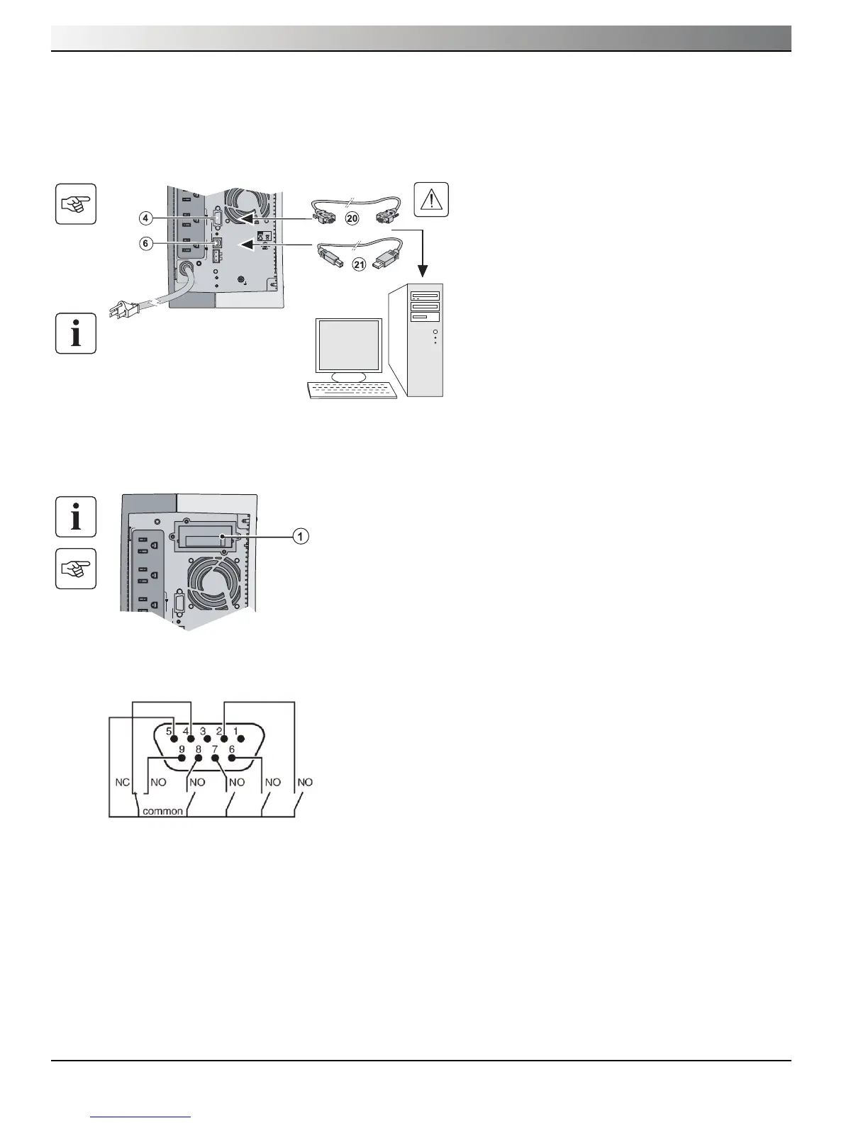
Installation of the communication cards (optional)
Characteristics of the contact communication port (optional)
When a signal is activated, the contact is closed between the common (pin 5) and the pin for the corresponding signal.
Please refer to the Network Management Card User Manual for the latest characteristics information.
Contact characteristics (optocoupler)
◗ Voltage: 48 V DC max
◗ Current: 25 mA max
◗ Power: 1.2 W
◗ Pin 1: Not used
◗ Pin 2: Battery fault
◗ Pin 3: UPS power off
◗ Pin 4: Load on Utility
◗ Pin 5: COMMON
◗ Pin 6: Load on bypass, when available on UPS
◗ Pin 7: Low battery
◗ Pin 8: UPS on, load powered
◗ Pin 9: Load on battery
n.o.: normally open contact
It is not necessary to shutdown the UPS before
installing a communication card.
1. Remove the slot cover (1) secured by screws.
2. Insert the communication card in the slot.
3. Secure the card cover with the two screws.
55K655K6
U.P.S.U.P.S.
R
AC OUTPUT AC OUTPUT
I max 12AI max 12A
AC INPUT
FAULT
SITE WIRING
U.S. PAT. NO. 6,094,363U.S. PAT. NO. 6,094,363
36Vdc, 9Ah36Vdc, 9Ah
PbPb
2
1
ProgrammableProgrammable
oror
RS232RS232
RPOROO RPO
Limited-access slot for the
communication card
1. Connect the RS232 (20) or USB (21) communica-
tion cable to the serial or USB port on the computer
equipment.
2. Connect the other end of the communication cable
(20) or (21) to the USB (6) or RS232 (4) communi-
cation port on the UPS.
The UPS can now communicate with MGE Office
Protection Systems power management software.
55K655K6
U.P.S.U.P.S.
R
AC OUTPUT
I max 12A
AC INPUTAC INPUT
FAULTFAULT
SITE WIRINGSITE WIRING
U.S. PAT. NO. 6,094,363U.S. PAT. NO. 6,094,363
36Vdc, 9Ah36Vdc, 9Ah
PbPb
2
1
ProgrammableProgrammable
oror
RS232RS232
ROO RPOROO RPO