EasyManua.ls Logo

MGL Avionics V16 User Manual

MGL Avionics V16
25 pages
To Next Page IconTo Next Page
Page #1 background imageLoading...
Page #1 background image
MGL Avionics
V16 Aviation band transceiver
User and Installation manual

Other manuals for MGL Avionics V16

Question and Answer IconNeed help?

Do you have a question about the MGL Avionics V16 and is the answer not in the manual?

MGL Avionics V16 Specifications

General IconGeneral
BrandMGL Avionics
ModelV16
CategoryTransceiver
LanguageEnglish

Summary

RF Exposure

FCC Statement

Industry Canada approval notes

General

Document history

Description

The Transmitter

The Receiver

The intercom system

RX playback feature

Power supply

Antenna

Digital control interfaces

Applicable standards

Specification table

General specifications

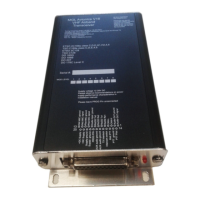
Lists compliance, FCC ID, documents, software, voltage, current, temperature, frequency, and power.

Audio input specifications

Microphone inputs

Describes gain range, impedance, and 8V DC bias for microphone inputs.

Auxiliary input

Covers gain range, maximum level, and input impedance for the auxiliary input.

Audio output specifications

Output impedance

Details the 8-ohm output impedance suitable for high impedance headphones.

Audio, RX and TX filters

Transmitter self protection

Transmitter low power option

Environmental qualification matrix

V16 Connector pinout

Typical connection diagrams

Audio wiring

Shows how to connect pilot and passenger audio pathways, including PTT and headphones.

Audio signal wiring advice

Control heads and options

Pinout for 3.18” Razor and 2.25” Vega transceiver control head

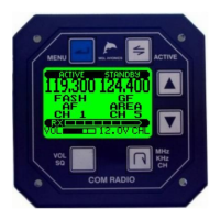
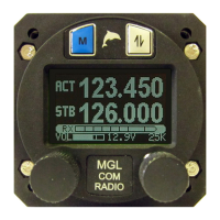
Details pin assignments for specific MGL Avionics control heads.

V16 with one or more control heads

V16 with a MGL Avionics EFIS system

V16 plus N16 Navigation receiver

V16 plus N16 with one or more control heads

Electrical state interfaces

PTT inputs

Explains the PTT input circuitry, activation logic, and RF filtering.

Intercom Switch/Playback switch

Details the function of the intercom switch for mic activation or RX playback.

TX Interlock

Describes the TX interlock's dual role as input and output for transmission control.

RF feedback – cause and elimination

TX signal delay

RS232 and CAN bus communication protocols

Setup menu

Menu items

VOX Configuration

Describes VOX sensitivity levels, bypass mode, and disabled states.

Microphone Gain Adjustment

Details the gain settings for pilot and passenger microphones for optimal audio.

Auxiliary Input Settings

Covers AUX input gain, muting levels, and option to disable the input.

TX Audio Mode Selection

Allows choosing between VOX-controlled or manual TX audio activation.

Menu items

TX Logic and Sidetone Settings

Configures TX prevention during RX and TX sidetone behavior.

TX Power Level Selection

Allows users to choose between 10W and 5W TX power output.

CAN Bus Addressing Configuration

Sets the CAN bus address for the V16 to identify it on the network.

Intercom Switch Functionality

Defines the intercom switch's role for microphone activation or playback.

System Information and Defaults

Displays firmware version, serial number, and option to reset to factory defaults.

VSWR Antenna checks and tuning

What is a good antenna match?

Reasons for a bad VSWR

Tuning antennas

Adjusting microphone levels

Mechanical dimensions

Materials

Related product manuals