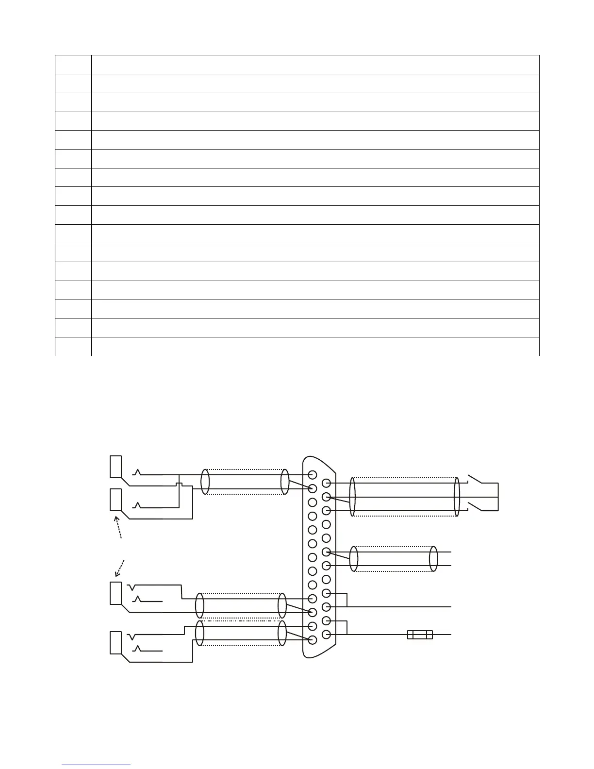
10 Pilot microphone
11 Audio input ground
12 PAX microphone
13 Audio input ground
14 PTT Pilot
15 PTT and intercom switch ground
16 PTT PAX
17 Intercom switch or RX audio playback (selected by configuration)
18 TX Interlock - connect to corresponding pin on second V16 transceiver
19 Auxiliary audio ground
20 Auxiliary audio input (Music, EFIS, mobile phone etc)
21 Programming pin. Leave this pin unconnected
22 Power supply ground
23 Power supply ground (connected internally to pin 22)
24 +12V to +28V DC power supply input
25 +12V to +28V DC power supply input (connected internally to pin 24)
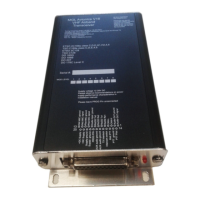
Typical connection diagrams
Audio wiring
This diagram shows a typical two place setup for a pilot and single passenger for two
1
13
14
25
Tip
Ring
Tip
Tip
Tip
Ring
Pilot PTT
PAX PTT
Pilot
Microphone
PAX
Microphone
Pilot
Headphones
PAX
Headphones
Isolate sleeves from each other and also
from any conductive surface
Auxiliary audio ground
Auxiliary audio signal
5A inline fuse
or circuit protector
Power supply ground
+12 to +28V DC supply