10
––– STEP 6 –––
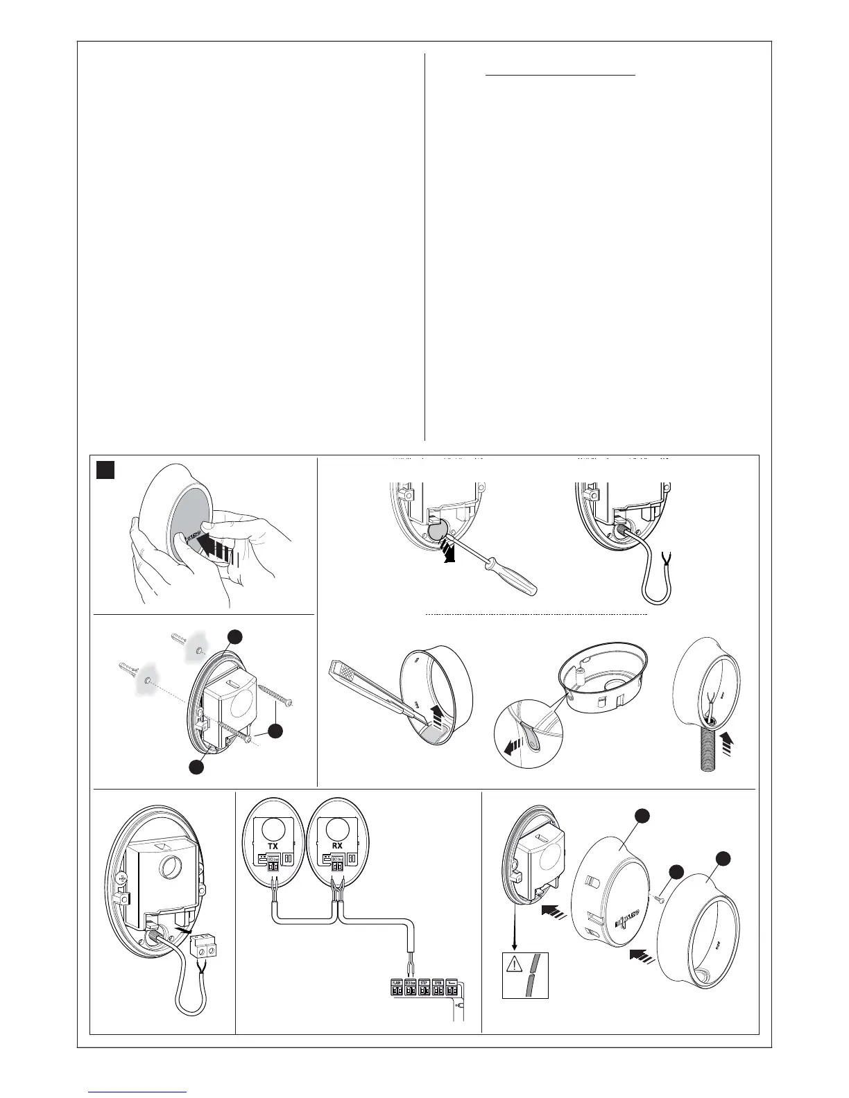
6.1 - INSTALLING AND CONNECTING PH100 PHOTO-
CELLS (fig. 21)
Warning: all installation operations must be performed with the system
disconnected from the power supply; if fitted, the PR1 backup battery
must also be disconnected.
Warnings: Take care not to damage the o-ring fitted (fig. 21-3) [A].
Observe the following directions when selecting the installation position
of the two elements that make up the photocell (TX and RX):
• Place them at a height of 40-60 cm from the ground, on both sides
of the area to be protected and as flush with the gate as possible (the
offset must not exceed 15 cm.).
• The point of installation must be provided with a conduit for the wires.
• Point the TX transmitter at the RX receiver, with a maximum misalign-
ment of 5°.
01. Remove the front glass panel (fig. 21-1).
02. Position the photocell at the point where the cable routing tube
arrives.
03. Trace the drilling points using the base as a reference. Drill the holes
in the wall using a hammer drill fitted with a 5mm bit and insert the 5
mm anchors in the wall.
04. Route the electric cables through the specific holes (pierce those
required): see fig. fig. 21-2.
05. Fix the base, using the related screws [B] in fig. 21-3 ensuring that
the hole on the base [C] in fig. 21-3 is aligned with the cable outlet.
Also 2 self-tapping screws are provided for fixing to surfaces with
different densities.
06. Connect the electrical cable in the related terminals of both TX and
RX (fig. 21-4). Connect the electrical cable in the relative terminals
of both TX and RX (fig. 21-5) and to the blue terminal on the control
board. No polarity needs to be observed.
07. Fix the covering shell [D] in fig. 21-6 with the two screws [E] in fig.
21-6 using a Phillips screwdriver. Lastly, insert the external cover [F]
in fig. 21-6 pressing it slightly to secure in place.
6.2 - INSTALLING AND CONNECTING THE FLASHING
LIGHT FL100 (fig. 20)
Select the position of the flashing light so that it is in the vicinity of the
gate in a visible location. It can be fixed on either a horizontal or vertical
surface. Fig. 22 shows the two options:
01. Remove the cover, unscrewing the screw if present;
02. Separate the base, unscrewing the screws present to route the
electric cables;
03. Trace the drilling holes using the base as a reference and ensuring
that the hole on the base is aligned with the cable outlet: vertical fix-
ing (A) or horizontal fixing (B);
04. Use a percussion drill to drill the wall, with a 6 mm tip, and insert 6
mm plugs;
05. Fix the base, using the related screws;
06. Connect the electric cables in the relative FLASH and “aerial” terminals
as shown in the figure: The terminals can be removed in order to facili-
tate the operations; make the connections and then reinsert them.
You do not need to observe any polarity on the FLASH terminal;
however, for the connection of the shielded cable to the aerial, con-
nect the sheath;
07. Insert the lamp holder in the base, taking care to press it down so
that it locks into place;
08. Secure the body of the flashing light to the fixing support and turn it
left until it clicks into place, then secure by means of the screw.
12
3
4
5
21
6
B
C
A
D
E
F