18
10.3 - ADDING OR REMOVING DEVICES
An automation using WS2S enables devices to be added or removed at
any time.
Caution! – Do not add devices before ensuring that they are fully
compatible with WS2S; for further details, contact the MHOUSE
technical assistance.
10.3.1 - ECSBus
ECSBus is a system that enables connections of ECSBus devices using
just two wires, which convey both electrical power and communication
signals. All the devices are connected in parallel on the 2 wires of the
ECSBus itself; each device is individually recognised because a univocal
address is assigned to it during the installation.
Photocells and other devices using this system can be connected to ECS-
Bus, such as safety devices, control buttons, indicator lights etc. For infor-
mation on ECSBus devices, refer to the MHOUSE catalogue or visit the
website www.mhouse.com.
The control unit recognises all the connected devices individually through a
suitable recognition process, and can detect all the possible abnormalities
with absolute precision. For this reason, each time a device connected to
ECSBus is added or removed the control unit must go through the recog-
nition process; see paragraph 10.3.3 “Recognition of Other Devices”.
10.3.2 - STOP Input
STOP is the input that causes immediate shutdown of the movement
(followed by a brief inversion of the manoeuvre). This input can be con-
nected to devices with contact types Normally Open (NO, as in the case
of the KS100 selector switch), Normally Closed (NC) or devices with a
constant resistance of 8.2kΩ, such as sensitive edges.
When set accordingly, more than one device can be connected to the
STOP input, also different from one another; see Table 7.
Note 1. The NO and NC combination can be obtained by placing the
two contacts in parallel, and placing an 8.2kΩ (resistance in series with
the NC contact (it is, therefore, possible to combine 3 devices: NO, NC
and 8.2kΩ).
Note 2. Any number of NO devices can be connected to each other in
parallel.
Note 3. Any number of NC devices can be connected to each other in
series.
Note 4. Only two devices with an 8.2kΩ constant resistance output can
be connected in parallel; multiple devices must be connected “in cas-
cade” with a single 8.2 kΩ termination resistance.
Caution! – If the STOP input is used to connect devices with safety
functions, only the devices with 8.2 kΩ constant resistance output
will guarantee the fail-safe category 3.
During the recognition stage the control unit, like ECSBus, recognises
the type of device connected to the STOP input; subsequently it com-
mands a STOP whenever a change occurs in the recognised status.
10.3.3 - Recognition of other devices
Normally the recognition of the devices connected to the ECSBus and
the STOP input takes place during the installation stage. However, if new
devices are added or old ones removed, the recognition process can be
gone through again by proceeding as follows:
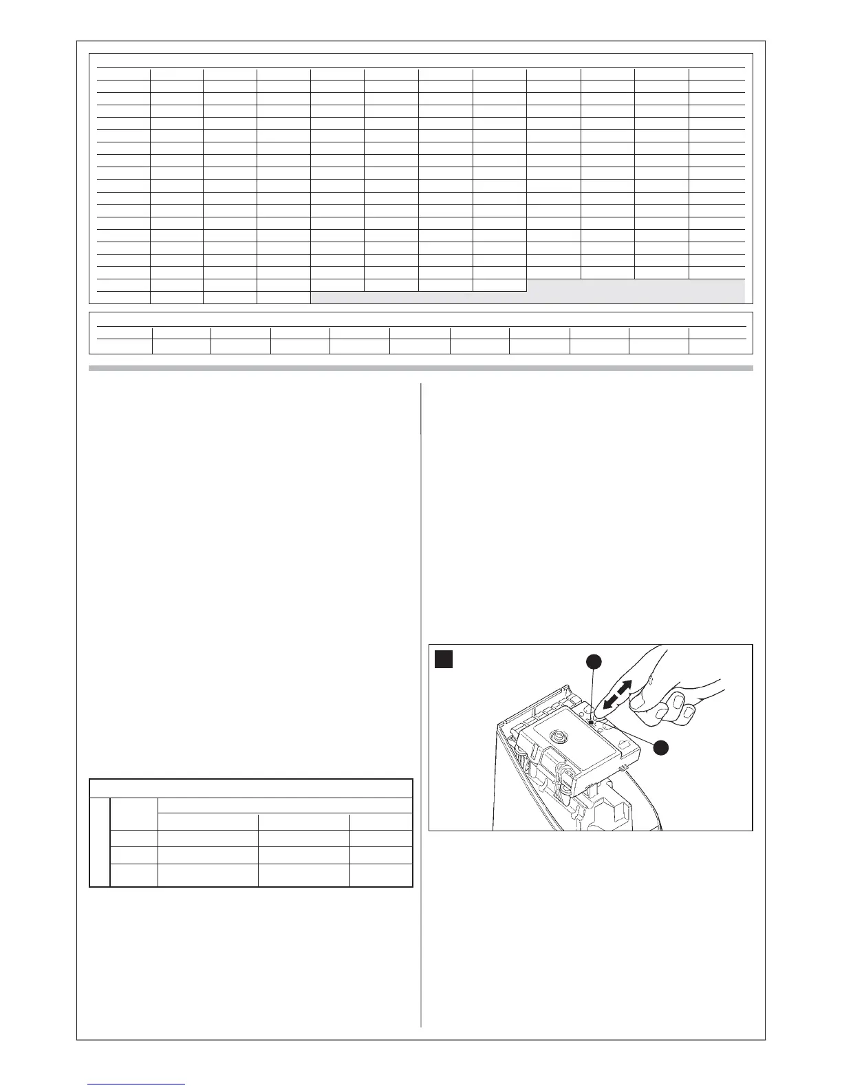
01. Press and hold key P2 [B] on the control unit for at least three sec-
onds (fig. 33), then release the key.
02. Wait a few seconds for the control unit to complete the device rec-
ognition phase.
03. At the end of the recognition phase the LED P2 [A] (fig. 33) should
switch off. If the P2 LED flashes it means that an error has occurred:
see paragraph 10.5 “Troubleshooting”.
04. After having added or removed a device the automation test must be
carried out again as specified in paragraph 8.1 “Testing”.
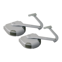
10.3.4 - Adding optional photocell
Additional photocells to those supplied with the WS2S can be installed
at any time. In systems for the automation of sliding gates they must be
installed as shown in fig. 34.
To ensure the correct recognition of the photocells by the control unit, the
former must be assigned addresses by means of electric jumpers. The
address assignment operation must be carried out on both TX and RX
(placing the electric jumpers in the same way) and it is important to check
that there are not any other pairs of photocells with the same address. The
photocells need to be assigned addresses to make sure that they are cor-
rectly recognised among the other ECSBus devices, and in order to assign
the performed function.
01. Open the housing of the photocell.
02. Identify the position in which they are installed according to Figure 70
and place the jumper according to Table 8.
33
A
B
TABLE B - Maximum number of cycles using exclusively battery power
K≤75 K=100 K=125 K=150 K=175 K=200 K=225 K=250 K=275 K=300 K≥325
741 556 445 371 318 278 247 222 202 185 171
TABLE A - Maximum possible number of cycles per day
Ed K≤75 K=100 K=125 K=150 K=175 K=200 K=225 K=250 K=275 K=300 K≥325
9500 123 92 74 61 53 46 41 37 33 31 28
9000 116 87 70 58 50 44 39 35 32 29 27
8500 109 82 66 55 47 41 36 33 30 27 25
8000 103 77 62 51 44 39 34 31 28 26 24
7500 96 72 58 48 41 36 32 29 26 24 22
7000 89 67 54 45 38 34 30 27 24 22 21
6500 83 62 50 41 35 31 28 25 23 21 19
6000 76 57 46 38 33 29 25 23 21 19 18
5500 69 52 42 35 30 26 23 21 19 17 16
5000 63 47 38 31 27 24 21 19 17 16 14
4500 56 42 34 28 24 21 19 17 15 14 13
4000 49 37 30 25 21 19 16 15 13 12 11
3500 43 32 26 21 18 16 14 13 12 11 10
3000 36 27 22 18 15 14 12 11 10 9 8
2500 29 22 18 15 13 11 10 9 8 7 7
2000 23 17 14 11 10 9 8 7 6 6 5
1500 16 12 10 8 7 6 5
1000 9 7 6
Area of use not recommended
1st device type:
NO NC 8.2 KΩ
NO In parallel (note 2) (note 1) In parallel
NC (note 1) In series (note 3) In series
8.2KΩ In parallel In series (note 4)
TABLE 7
2nd device type: