17
10.2.3 - Maximum possible number of cycles per day
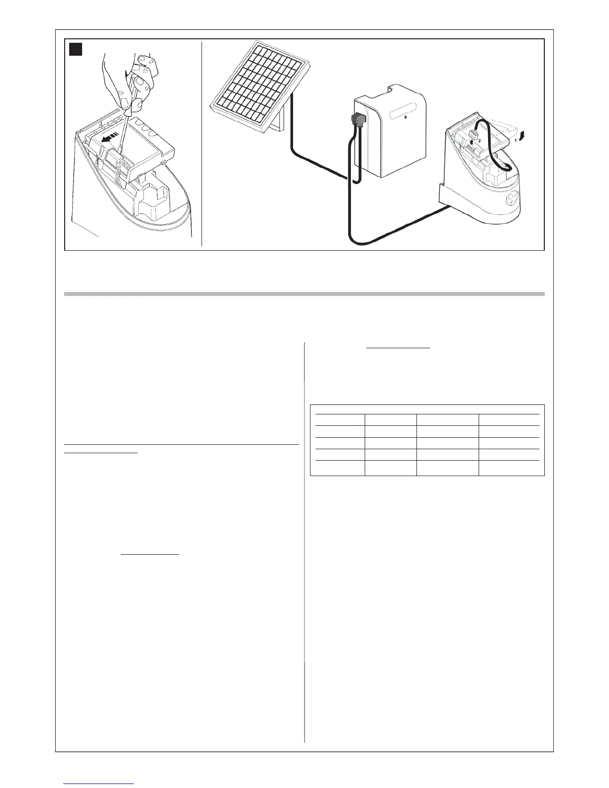
This product is specifically designed to operate also with the PF solar
power supply system. Special technical provisions have been envisaged
to minimise energy consumption when the automation is stationary, by
turning off all devices not essential to operation (for example photocells
and the key-operated selector switch). In this way all energy available and
stored in the battery is used to move the gate.
Caution! – When the automation is powered by the solar power
system “PF”, IT MUST NEVER BE POWERED at the same time by
the mains.
Application limits: maximum possible number of cycles per day within
a set period of the year.
The PF solar power system enables complete power autonomy of the
automation, until the energy produced by the photovoltaic panel and
stored in the battery remains above the amount consumed during gate
manoeuvres. A simple calculation enables an estimate of the maximum
number of cycles per day performed by the automation in a certain period
of the year, provided that a positive energy balance is maintained.
The first step in calculating the energy available is dealt with in the PF
instruction manual; the second step in calculating the energy consumed
and therefore the maximum number of cycles per day, is dealt with in this
chapter.
Calculating the energy available
To calculate the energy available (refer also to the PF instruction manual)
proceed as follows:
01. On the terrestrial map supplied in the PF kit instruction manual,
locate the point of system installation; then read the value Ea and
the degrees of latitude of this location (E.g. Ea = 14 and degrees =
45°N)
02. On the graphs (North or South) supplied in the PF kit instruction man-
ual, locate the curve for the location’s latitude (e.g. 45°N)
03. Choose the period of the year on which to base the calculation, or
select the lowest point of the curve to calculate the worst period
of the year; then read the corresponding value Am (e.g. December,
January: Am= 200)
04. Calculate the value of energy available Ed (produced by the panel) mul-
tiplying: Ea x Am = Ed (e.g. Ea = 14; Am = 200 therefore Ed = 2800)
Calculating the energy consumed
To calculate the energy consumed by the automation, proceed as follows:
05. On the table below, select the box corresponding to the intersection
between the line with the weight and the column with the opening
angle of the gate leaf. The box contains the value of the severity
index (K) for each manoeuvre (e.g. WS2S with a leaf of 130 Kg and
opening of 100°; K = 106).
(*) value B specified in the table represents the optimal value; if B is a lower
value, add 20% to value K specified in the table.
06. On the table A below, select the box corresponding to the intersec-
tion between the line with the Ed value and the column with the K
value. The box contains the maximum possible number of cycles per
day (e.g. Ed = 2800 and K= 106; cycles per day ≈ 22)
If the number obtained is too low for the envisaged use or is located in the
“area not recommended for use”, the use of 2 or more photovoltaic pan-
els may be considered, or the use of a photovoltaic panel with a higher
power. Contact the Mhouse technical assistance service for further infor-
mation.
The method described enables the calculation of the maximum possible
number of cycles per day that can be completed by the automation while
running on solar power. The calculated value is considered an average
value and the same for all days of the week. Considering the presence of
the battery, which acts as an energy “storage depot”, and the fact that the
battery enables automation autonomy also for long periods of bad weather
(when the photovoltaic panel produces very little energy) it may be possible
to exceed the calculated maximum possible number of cycles per day, pro-
vided that the average of 10-15 days remains within the envisaged limits.
Table B below specifies the maximum possible number of cycles,
according to the manoeuvre’s severity index (K), using exclusively the
energy stored by the battery. It is considered that initially the battery is
completely charged (e.g. after a prolonged period of good weather or
recharging via the optional PCB power supply unit) and that the manoeu-
vres are performed within a period of 30 days.
When the battery runs out of the stored energy, the led starts to indicate
the battery low signal by flashing briefly every 5 seconds, accompanied
by a “beep”.
Opening angle
Leaf weight ≤95° (B≈200)* 95÷105° (B≈130)* 105÷110°(B≈70)*
< 75 Kg 54 72 101
75-120 Kg 65 84 134
120-150 Kg 80 106 196
150-180 Kg 105 150 320
32
1 2