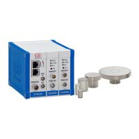
The capaNCDT 6200 series, including models DT6220, DT6222, and DT6230, is a high-precision measurement system designed for industrial environments. It is primarily used for measuring displacement, distance, movement, and thickness, as well as for determining the position of parts or machine components. The system is engineered to operate within specified technical limits and requires additional safety precautions for critical applications.
Function Description:
The capaNCDT 6200 system utilizes capacitive sensors to perform non-contact measurements. It consists of a controller, demodulator modules, and sensors. The controller processes the signals from the sensors and provides various output options, including analog signals and digital communication via Ethernet or EtherCAT. A key feature of this system is its synchronization capability, which allows multiple sensors and controllers to operate simultaneously without interference, even when the target object is not grounded. This is particularly beneficial in applications where grounding the target is difficult or impossible. The system supports multi-channel operation, with each channel corresponding to a connected sensor. Users can configure measuring ranges, apply mathematical functions for scaling and linking channels, and monitor measurement values through a web-based interface or dedicated software (sensorTOOL).
Important Technical Specifications:
- Temperature Range (Controller): Operation: +10 to +60 °C (+50 to +140 °F); Storage: -10 to +75 °C (+14 to +167 °F).
- Temperature Range (Sensor):
- CS series: Operation: -50 to +200 °C (-58 to +392 °F); Storage: -50 to +200 °C (-58 to +392 °F).
- CSG series: Operation: -50 to +100 °C (-58 to +212 °F); Storage: -50 to +100 °C (-58 to +212 °F).
- Temperature Range (Sensor Cable):
- CCgxC, CCgxC/90: Operation: -20 to +100 °C (-4 to +212 °F); Storage: -20 to +80 °C (-4 to +176 °F).
- CCgxB, CCgxB/90, CCmxC, CCmxC/90, CCmxB, CCmxB/90: Operation: Up to 10,000 operating hours; Permanent: -100 to +200 °C (-148 to +392 °F); Storage: -50 to +200 °C (-58 to +392 °F).
- Protection Class: IP40.
- Humidity: 5-95% (non-condensing).
- Ambient Pressure: Atmospheric pressure.
- Power Supply (PC6200-3/4): +24 VDC.
- Analog Output (SCACx/4): V_OUT (Load min. 10 kOhm), I_OUT (Load max. 500 Ohm).
- Threaded Rod Lengths (Demodulator Modules): 1 module: 59 mm; 2 modules: 84 mm; 3 modules: 109 mm; 4 modules: 134 mm.
- Measuring Range: Configurable between 0 and 1,000,000 µm.
- Low-Pass Filter: 20 Hz (configurable via Ethernet).
- Communication: Ethernet, EtherCAT (switchable via hardware or software).
- IP Address (Factory-set): 169.254.168.150.
Usage Features:
- Sensor Installation: Sensors can be installed flush, protruding, or recessed, depending on the sensor series (e.g., CSE series). Care must be taken to avoid scratching the sensor front face during installation.
- Mounting Options:
- Radial Spot Clamping (Cylindrical Sensors): Simple mounting using a plastic grub screw, suitable for locations free of impact or vibration. Metal grub screws are not permitted to avoid sensor damage.
- Clamping Around Circumference (Cylindrical Sensors): High reliability assembly with a clamping collet, ideal for machines and production facilities.
- Flat Sensors: Screwed connections from either the top or bottom.
- Demodulator Module Insertion: The modular design allows for easy expansion of the system by adding demodulator modules. This involves loosening sleeve nuts, replacing threaded rods with longer ones from the conversion kit, and connecting flat strip connections between modules.
- Grounding: The system features a grounding connection on the housing cover. For non-contact measurements with synchronized DL62xx demodulators, target grounding is often not required, simplifying setup in many applications.
- Synchronization: All sensors within a single controller are synchronized. Multiple DT6230 series controllers can be synchronized externally using an SC6000-x cable to prevent mutual interference, enabling multi-channel systems.
- Configuration and Monitoring: The system can be configured and monitored via a web browser interface or the sensorTOOL software. This includes setting measuring ranges, applying math functions (Offset and Factor), and viewing real-time measurement data. The web interface provides additional help functions and allows for parameter descriptions.
- LED Indicators: LEDs on the controller provide visual feedback on system status:
- Range (Green): Target within measuring range.
- Range (Red): Measuring range exceeded.
- LP Filter (Off): Default strip width active.
- LP Filter (Red): 20 Hz low-pass filter enabled.
- Zero (Off): Zero potentiometer in base position.
- Zero (Red): Zero potentiometer misaligned.
- Ethernet/EtherCAT Switching: The DT6230 base module includes a hardware switch (EN/EN/EC) to select between Ethernet and EtherCAT interfaces, or to allow software control. Changes take effect after restarting the controller.
Maintenance Features:
- Sensor Surface Cleaning: The sensor surface must always be kept clean. Before cleaning, the power supply must be disconnected to prevent static discharge and injury. Clean with a damp cloth and then dry the surface.
- Recalibration: If the target changes or after long operating periods, minor losses in operating quality may occur. These can be corrected by recalibrating the system.
- Troubleshooting: In case of a fault that cannot be clearly identified, the complete measurement system should be sent for repair. If only a component (controller, sensor, or cable) is defective, only the affected parts need to be sent for repair or exchange.
- Cable Protection: The sensor cable must be protected against damage to prevent destruction of the sensor or failure of the measurement system. Tension on the cable is not permitted.
- Electrostatic Discharge Protection: When handling demodulator modules, only touch the housing, not the electronics, to avoid electrostatic discharges.
- Supply Voltage: Ensure the supply voltage does not exceed specified limits to prevent damage to the sensor and/or controller.
- Impact Protection: Avoid shocks and impacts to the sensor and controller to prevent damage or destruction.
- Unauthorized Modifications: Unauthorized structural and/or technical modifications or alterations to the product are not permitted. Repairs must be carried out exclusively by MICRO-EPSILON.