Do you have a question about the MICRO-EPSILON CS02 and is the answer not in the manual?
Explains the meaning of symbols and lists critical safety warnings.
Details CE marking directives and specifies the system's intended application.
Lists environmental conditions required for operation and storage.
Explains the capacitive measurement principle of the system.
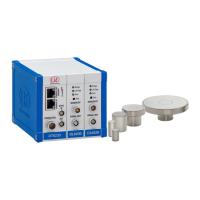
Describes the system's components and provides a block diagram.
Lists available sensors, their ranges, and details sensor cable specifications.
Provides information on basic and demodulator controller modules.
Presents detailed technical specifications and available options.
Lists items included in the delivery package and unpacking instructions.
Specifies storage temperature and humidity requirements.
Outlines precautions for installation and general sensor mounting.
Details radial point, circumferential clamping, and flat sensor mounting.
Explains the sensor cable connection and locking mechanism.
Provides dimensional drawings for controller units and modules.
Guides on how to insert additional demodulator modules.
Explains the requirements for ground connection and earthing.
Illustrates electrical connections and details pin assignments for various functions.
Guides initial device startup and describes operating and display elements.
Explains the function of each LED indicator on the controller.
Details the function of the zero-potentiometer for analog output adjustment.
Explains how to switch interfaces and change the limit frequency.
Describes the different triggering modes available for measurements.
Introduces measurement averaging techniques for improved resolution.
Details Ethernet connection setup, requirements, and IP configuration.
Describes the structure and format of transmitted measurement data.
Outlines operating modes, data rate, and filter/averaging settings.
Lists commands for data rate, trigger, linearization, math functions, and settings.
Explains how to operate the controller via Ethernet using web pages.
Covers channel information, measuring range, linearization, and math functions.
Details measurement modes, data rates, filters, and trigger settings.
Covers language, user level, password, Ethernet, and import/export settings.
Guides on how to update the controller's firmware.
Introduces the EtherCAT interface, its protocol, and capabilities.
Explains how to switch between Ethernet and EtherCAT interfaces.
Describes the deflection method for fast events and tolerance monitoring.
Describes the compensation method for constant or slowly changing distances.
Provides instructions for sensor surface maintenance and cleaning.
Instructs users on how to contact the manufacturer for repairs.
Outlines the manufacturer's liability for material defects.
Details the warranty period and conditions for repairs or replacements.
Provides guidelines for the proper decommissioning and disposal of the device.
Lists the components included in the conversion kit.
Describes the PC6200-3/4 power supply and trigger cable.
Lists optional accessories such as calibration fixtures.
Details function and linearity check-out services.
Lists the default analog and digital settings configured at the factory.
Illustrates the effect of tilt angle on measuring range deviation.
Shows measuring range deviation when measuring on narrow targets.
Illustrates measuring value deviation on ball-shaped and cylindrical targets.
Explains the structure and components of EtherCAT frames.
Lists the supported EtherCAT services for data reading and writing.
Explains addressing methods and the function of FMMUs in EtherCAT.
Describes the role of Sync Managers in ensuring data consistency.
Explains the different states of the EtherCAT state machine.
Details the CANopen communication profile over EtherCAT.
Explains process data object mapping for real-time data transmission.
Explains Service Data Objects (SDOs) for parameter access.
Introduces the CANopen over EtherCAT object directory structure.
Lists standard communication objects defined by CiA DS-301.
Lists manufacturer-specific objects for controller and channel information.
Describes the format of transmitted measuring values as Float.
Guides EtherCAT configuration using the Beckhoff TwinCAT Manager.
| Brand | MICRO-EPSILON |
|---|---|
| Model | CS02 |
| Category | Measuring Instruments |
| Language | English |